 |
|||
|
|
|||
|
Page Title:
SILICON VERSION A5200A SQUELCH AMPLIFIER ALINEMENT, NEW SQUELCH LEVEL. |
|
||
| ||||||||||
|
|  TM 11-5820-401-34-3/0967-LP-432-3060
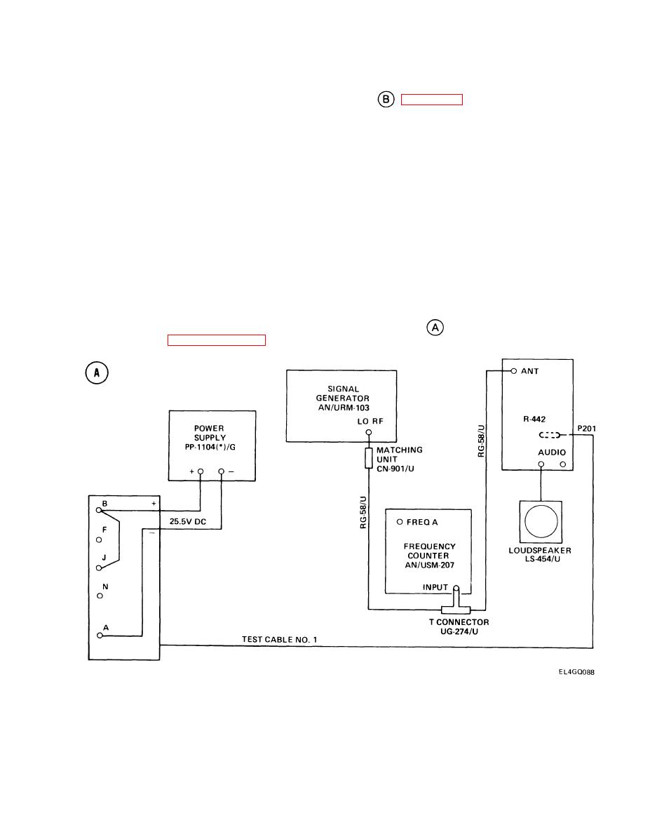
5-25. A5200 SQUELCH AMPLIFIER ALINEMENT, NEW SQUELCH LEVEL. (CONT)
1.
Lift R-442/VRC A3000 tray (1). (See test setup diagram
2.
Set ME-30(*)/U to 10-volt scale.
3.
Connect ME-30(*)/U positive lead to TP5008 (2), and negative lead to ground.
4.
Turn AN/URM-103 DEVIATION control clockwise until ME-30(*)/U reads 4 vat.
5.
Remove ME-30(*)/U positive lead.
6.
Adjust NEW Squelch Resistor R5217 (3) until R-442/VRC CALL light just comes on.
5-26. SILICON VERSION A5200A SQUELCH AMPLIFIER ALINEMENT, NEW SQUELCH LEVEL.
PURPOSE. This procedure adjusts the receiver sensitivity to the 150-Hz NEW SQUELCH tone.
TEST EQUIPMENT AND MATERIALS
Signal Generator AN/URM-103
Matching Unit CN-901/U
Frequency Counter AN/USM-207
T-Connector UG-274/U
Power Supply PP-1104(*)/G
Loudspeaker LS-454/U
Voltmeter ME-30(*)/U
T e s t Cable No. 1
TEST SETUP. Connect the equipment as shown in test setup diagram
. Remove R-442/VRC
top cover. (See paragraph 2-7.)
INITIAL EQUIPMENT CONTROL SETTINGS. Set equipment controls as indicated in the following
table. When using alternate equipment, inject 2000-v rf at 64 MHz, 150-Hz modulation; deviation as
per alinement requirements.
5-121
|
|
Privacy Statement - Press Release - Copyright Information. - Contact Us |
