 |
|||
|
|
|||
|
Page Title:
Audio Response Test (Normal Mode) Modulating Frequencies |
|
||
| ||||||||||
|
|  TM 11-5820-401-3/0967-LP-432-3060
4-8.
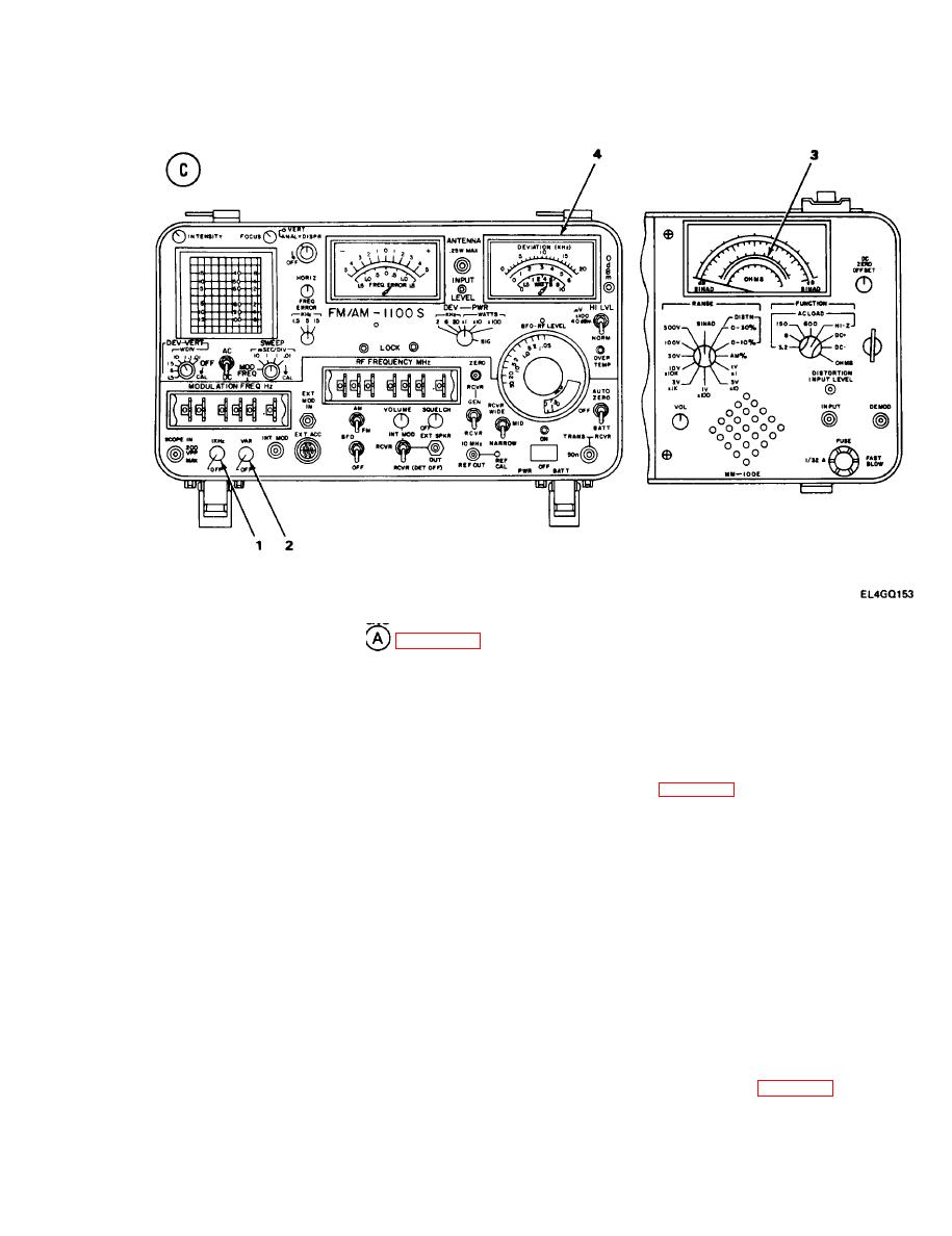
RECEIVER AUDIO RESPONSE TEST (NORMAL MODE). (CONT)
TEST PROCEDURE
1. Connect MM-100E attenuated probe A to MK-1978/VRC SPKR jack; connect probe B to GND.
(See test setup diagram
2. Adjust R-442/VRC VOLUME control until MM-100E red db scale indicates zero db.
3. Turn AN/GRM-114A 1 kHz/OFF control (1) to OFF.
4. Adjust AN/GRM-114A VAR/OFF control (2) for zero-db indication on red db scale of
MM-100E (3).
STANDARD. The AN/GRM-114A DEVIATION meter (4) should indicate 8 kHz.
5. If DEVIATION meter does not indicate 8 kHz, see troubleshooting chart 4-9.
Audio Response Test (Normal Mode) Modulating Frequencies
6. Set AN/GRM-114A MODULATION FREQ Hz thumbwheels to modulating frequencies listed
below. Note MM-100E and AN/GRM-114A DEVIATION meter indications.
a.
2000 Hz
b.
3000 Hz
c.
500 Hz
d.
1000 Hz
STANDARD. MM-100E should indicate 0 2 db and NWGRM-114A DEVIATION meter should
indicate 8 kHz at each frequency.
7. If, at any frequency, MM-100E indicates more than 2 db above or below 0 db, or if
AN/GRM-114A DEVIATION meter does not indicate 8 kHz, see troubleshooting chart 4-9.
4-21
|
|
Privacy Statement - Press Release - Copyright Information. - Contact Us |
