 |
|||
|
|
|||
|
|
|||
| ||||||||||
|
|  TM 11-5820-401-34-3/0967-LP-432-3060
3-26. SILICON VERSION A5200A SQUELCH AMPLIFIER ALINEMENT, NEW SQUELCH LEVEL. (CONT)
ALINEMENT PROCEDURE
NOTE
64 MHz. The rf level must be increased temporarily to enable the frequency counter to
display. Adjust the AN/URM-103 RF TUNING control as necessary, reset to 2000-v rf
level; then disconnect the T-connector from the counter.
1.
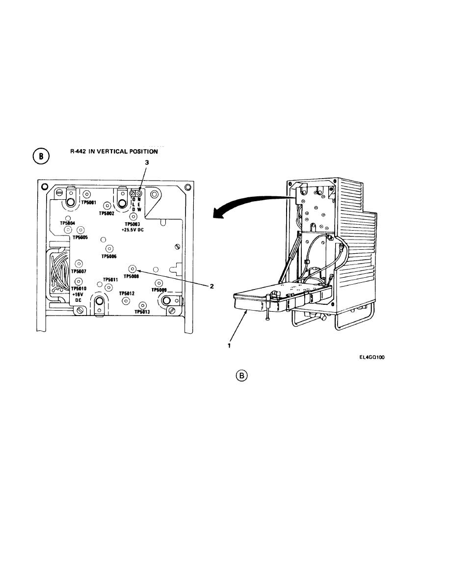
Lift R-442/VRC A3000 tray (1). (See test setup diagram
)
2.
Set ME-30(*)/U to 0.3-volt scale.
3.
Connect ME-30(* )/U positive lead to TP5008 (2), and negative lead to ground.
4.
Turn AN/URM-103 DEVIATION control clockwise until ME-30(*)/U reads 0.20 0.01 vac.
Adjust NEW Squelch Resistor 5207(3) until R-442/VRC CALL light just comes on.
5.
Turn AN/URM-103 DEVIATION control counterclockwise until ME-30(*)/U reads
6.
0.15 0.01 vac. R-442/VRC CALL light should be off.
NOTE
If CALL light does not go off in step 6, repeat steps 4 and 5.
3-122
|
|
Privacy Statement - Press Release - Copyright Information. - Contact Us |
