 |
|||
|
|
|||
|
|
|||
| ||||||||||
|
|  TM 11-5820-401-34-3/0967-LP-432-3060
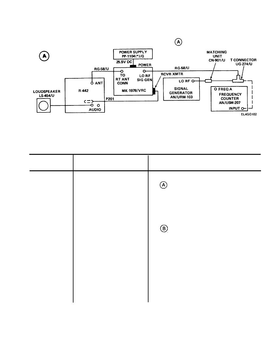
3-18. TUNER A1000 ALINEMENT.
TEST SETUP. Connect equipment as shown in test setup diagram
.
INITIAL EQUIPMENT CONTROL SETTINGS. Set equipment controls as indicated in the following
table. If using alternate equipment, inject unmodulated rf carrier at 30,52,53,75,65, and 52 MHz,
in that order. Rf output level will vary according to alinement requirements.
CONTROL AND SWITCH SETTINGS
POSITION/SETTING
CONTROL OR SWITCH
EQUIPMENT
ON-RESET
POWER
R-442/VRC
BAND
30.00
MC-TUNE-KC
NEW OFF
SQUELCH
Fully clockwise
VOLUME
MOD OFF
FUNCTION
AN/URM-103
LO, 0-10 KUV
RF OUTPUT
Set to zero output
LO RF UV
BAND SWITCH
30.00
RF TUNING
OPERATE
OPERATE/OFF/STAND BY
TRACK
POWER
AN/USM-207
MIN (fully counterclockwise)
DISPLAY
PLUG IN
Sensitivity
FREQ
FUNCTION
103 (black knob)
GATE TIME
DIRECT
DIRECT/HETERODYNE
0.3 V MAX (both switches to left)
IN PUT
100
FREQUENCY TUNING-MC
3-99
|
|
Privacy Statement - Press Release - Copyright Information. - Contact Us |
