 |
|||
|
|
|||
|
|
|||
| ||||||||||
|
|  TM 11-5820-401-34-3/0967-LP-432-3060
3-17.
LOCAL OSCILLATOR A1500 ALTERNATE ALINEMENT PROCEDURE. (CONT)
4.
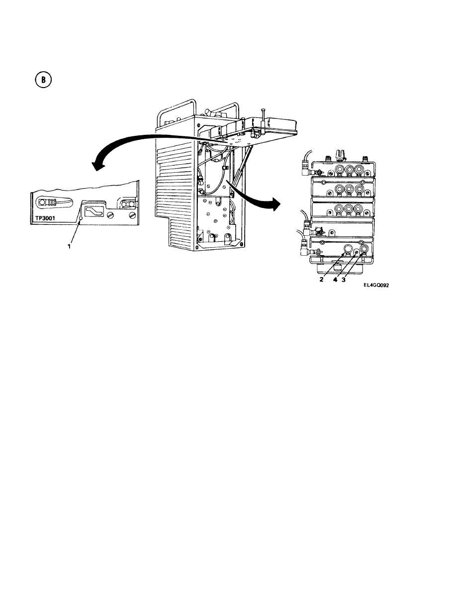
Adjust L1501 (3) for 63.50-MHz reading on counter and zero vdc (midscale) on ME-26( *)/U.
5.
Set R-442/VRC MC-TUNE-KC control to 42.00 MHz.
Adjust C1501 (4) for 53.50-MHz reading on counter and zero vdc (midscale) on ME-26(*)/U.
6.
7.
Set R-442/VRC MC-TUNE-KC control to 30.00 MHz.
Repeat steps 2 through 6 until ME-26(*)/U reads zero vdc for all three frequencies.
8.
Reconnect P1004 to J1004.
9.
3-18.
TUNER A1000 ALINEMENT.
PURPOSE. This procedure tunes the A1000 assembly to produce maximum amplification of low-level
signals and maximum attenuation of noise.
TEST EQUIPMENT AND MATERIALS
Signal Generator AN/URM-103
Matching Unit CN-901/U
Frequency Counter AN/USM-207
T-Connector UG-274/U
Power Supply PP-1104(*)/G
Loudspeaker LS-454/U
Maintenance Kit MK-1978/VRC
Voltmeter ME-30(*)/U
3-98
|
|
Privacy Statement - Press Release - Copyright Information. - Contact Us |
