 |
|||
|
|
|||
|
|
|||
| ||||||||||
|
|  TM 11-5820-401-34-3/0967-LP-432-3060
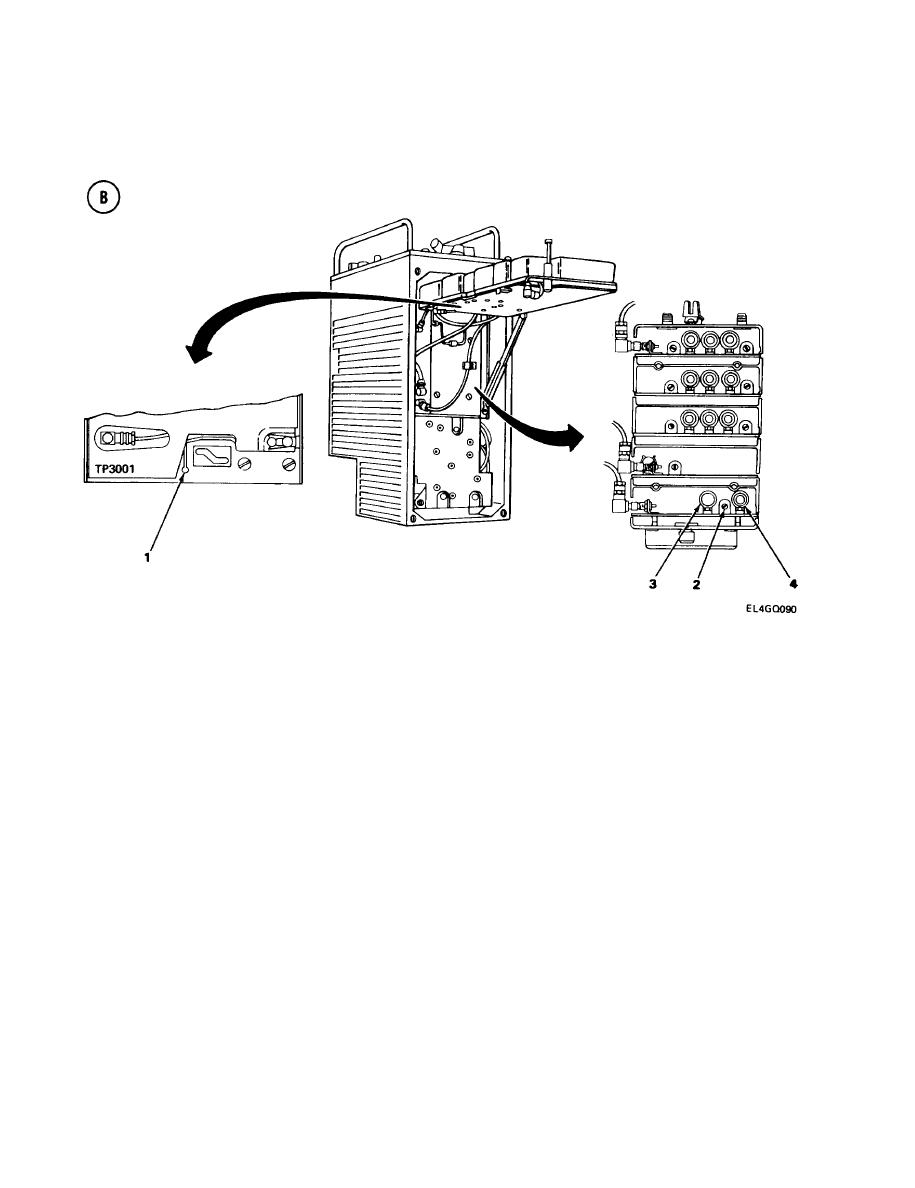
3-16. LOCAL OSCILLATOR A1500 ALINEMENT. (CONT)
ALINEMENT PROCEDURE
Connect ME-26(*)/U positive lead to TP3001 (1) and negative lead to ground.
1.
2.
Adjust C1501 (2) for clear audio tone and zero-volt reading on ME-26(*)/U.
3.
Set R-442/VRC MC-TUNE-KC control to 30.00 MHz.
4.
Connect AN/USM-207 frequency counter to T-connector.
Adjust AN/URM-103 RF TUNING control for 30.00-MHz output. Check frequency on counter.
5.
Adjust L1502 (3) for clear audio tone and zero-volt reading on ME-26(*)/U.
6.
7.
Set R-442/VRC MC-TUNE-KC control to 52.00 MHz.
8.
Connect frequency counter to T-connector.
Adjust AN/URM-103 RF TUNING control for 52.00-MHz output.
9.
10.
Adjust L1501 (4) for clear audio tone and zero-volt reading on ME-26(*)/U.
Repeat steps 2 through 10 to make sure that local oscillator tracks with no more than 0.5-vdc
11.
error signal required in any of the three test frequencies.
NOTE
If the ME-26(*)/U indicates more than + 0.5 vdc or less than -0.5 vdc in any frequency,
and repetition of steps 2 through 10 does not correct the problem, replace the A1500
assembly.
3-96
|
|
Privacy Statement - Press Release - Copyright Information. - Contact Us |
