 |
|||
|
|
|||
|
Page Title:
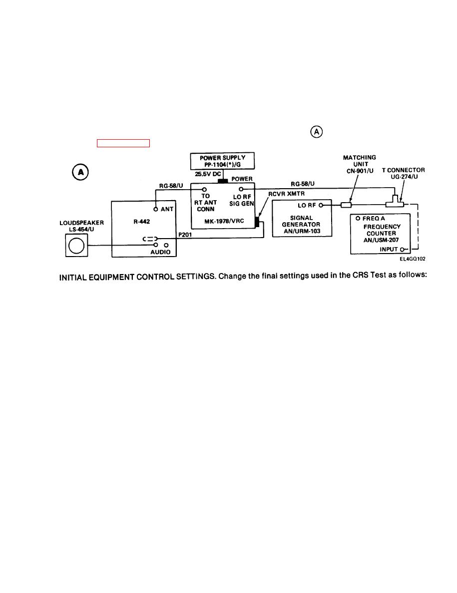
INITIAL EQUIPMENT CONTROL SETTINGS |
|
||
| ||||||||||
|
|  TM 11-5820-401-34-3/0967-LP-432-0306
3-16. LOCAL OSCILLATOR A1500 ALINEMENT. (CONT)
TEST EQUIPMENT AND MATERIALS
Matching Unit CN-901/U
Signal Generator AN/URM-103
T-Connector UG-274/U
Frequency Counter AN/USM-207
Loudspeaker LS-454/U
Power Supply PP-1104(*)/G
Multimeter ME-26(*)/U
Maintenance Kit MK-1978/VRC
TEST SETUP. Connect the equipment as shown in test setup diagram
. Remove R-442/ VRC top
cover. (See paragraph 3-7.) Connect P1004 to J1004 on the A1000 tray.
Set AN/URM-103 RF OUTPUT switch to 0-10 KUV.
1.
2. Adjust AN/URM-103 RF TUNING control for 42.00-MHz output.
NOTE
42.00 MHz. The rf level must be increased temporarily to enable the frequency counter
to display. Adjust the AN/URM-103 RF TUNING control as necessary, reset to 100-v rf
level; then disconnect the T-connector from the counter.
3. Set R-442/VRC MC-TUNE-KC control to 42.00 MHz.
4. Adjust AN/URM-103 DEVIATION control for 8-kHz reading on DEVIATION KHZ meter.
3-95
|
|
Privacy Statement - Press Release - Copyright Information. - Contact Us |
