 |
|||
|
|
|||
|
Page Title:
CRYSTAL REFERENCE SYSTEM (CRS) TEST. |
|
||
| ||||||||||
|
|  TM 11-5820-401-34-3/0967-LP-432-3060
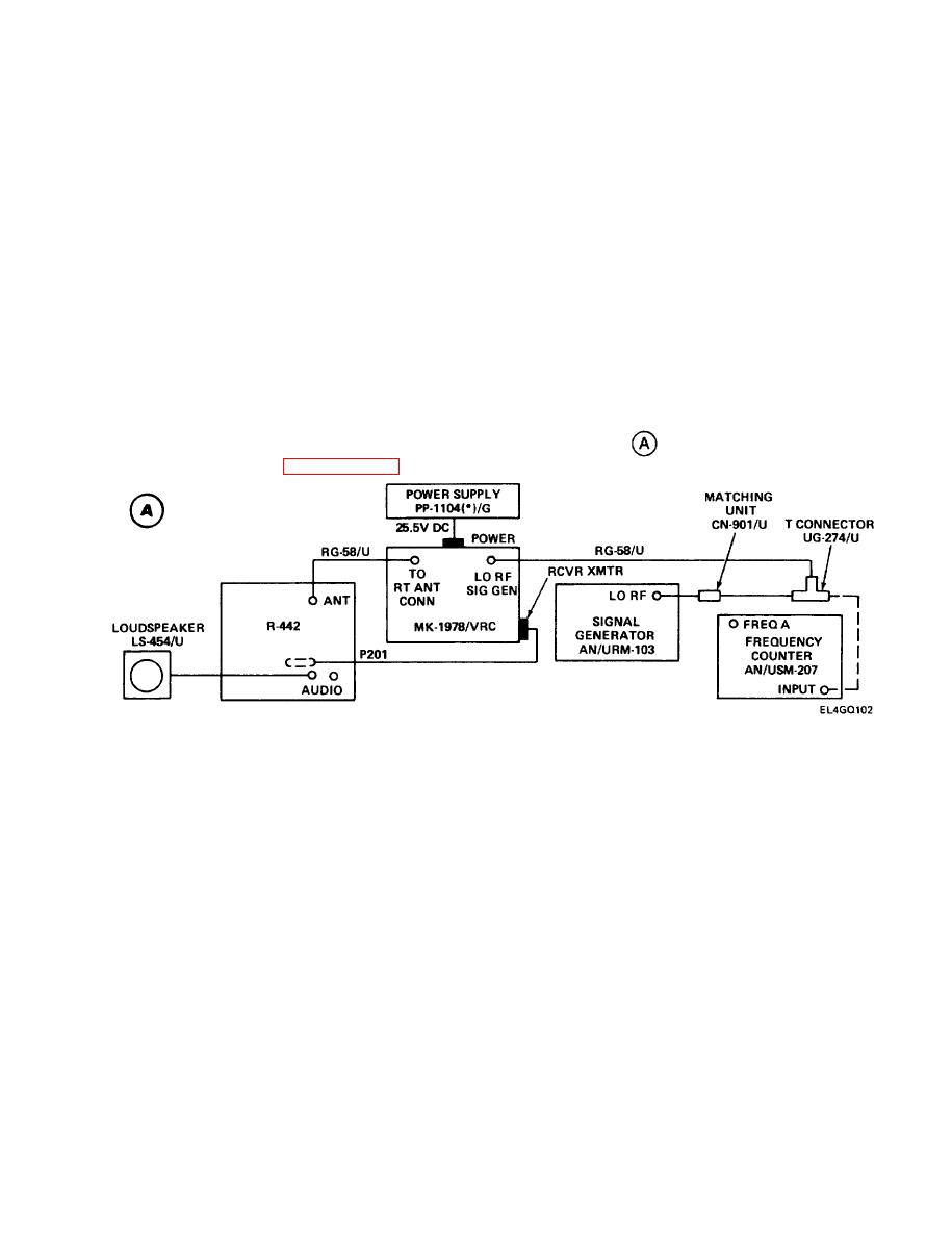
3-15. CRYSTAL REFERENCE SYSTEM (CRS) TEST.
PURPOSE. This test is performed to make sure that the local oscillator will not be pulled off frequen-
cy by a malfunctioning CRS. Steps 1 through 8 involve a quick check to determine whether the CRS is
putting out an incorrect error signal causing improper local oscillator frequency and loss of audio
tone. The remaining steps are done with the local oscillator disconnected from the CRS in order to
check CRS performance in response to a nonfluctuating 42.00-MHz signal generator output. If the
CRS passes the second part of the test, it will be able to correct normal fluctuation in Iocal oscillator
frequency.
TEST EQUIPMENT AND MATERIALS
T-Connector UG-274/U
Signal Generator AN/URM-103
Loudspeaker LS-454/U
Frequency Counter AN/USM-207
Multimeter ME-26(*)/U
Power Supply PP-1 104 (*)/G
Amphenol Adapter M-39012/16
Maintenance Kit MK-1978/VRC
Matching Unit CN-901/U
TEST SETUP. Connect the equipment as shown in test setup diagram
. Remove R-442/ VRC top
and bottom covers. (See paragraph 2-7.)
INITIAL EQUIPMENT CONTROL SETTINGS. Set equipment controls as indicated in the following
table. If using alternate equipment, inject 100-v rf at 30 MHz, 1-kHz modulation, and 8-kHz
deviation.
3-91
|
|
Privacy Statement - Press Release - Copyright Information. - Contact Us |
