 |
|||
|
|
|||
|
|
|||
| ||||||||||
|
|  TM 11-5820-401-34-3/0967-LP-432-3060
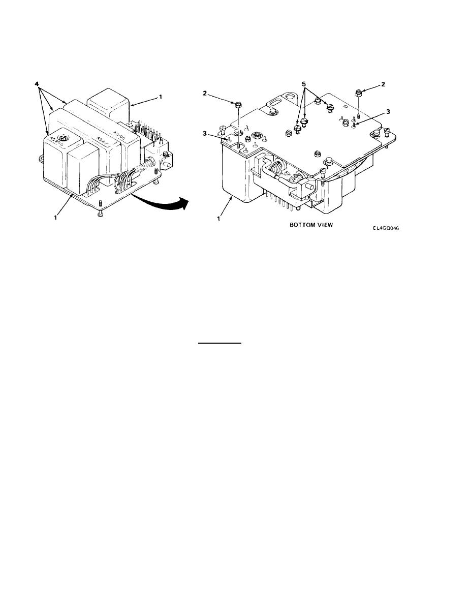
2-20.
A5000 MODULE AND ASSEMBLY REPLACEMENT. (CONT)
INSTALLATION (CONT)
NOTE
Modules FL5001 and T5001 are secured with locknuts and are soldered to printed circuit
board. Steps 4, 5, and 6 are typical for both modules.
Module number location is stamped on board.
4. Position module (1) on board and install locknuts (2).
5. Using wrench, tighten locknuts (2).
CAUTION
Care must be taken when performing next step to prevent damage to printed circuit
board.
NOTE
Modules A5100 through A5300 are secured with captive screws. Steps 7 and 8 are
typical for all modules.
Module number is stamped on board.
7. Carefully position module (4) on pins and push into place.
8. Using screwdriver, tighten captive screws (5).
2-44
|
|
Privacy Statement - Press Release - Copyright Information. - Contact Us |
