 |
|||
|
|
|||
|
|
|||
| ||||||||||
|
|  TM 11-5820-401-34-3/0967-LP-432-3060
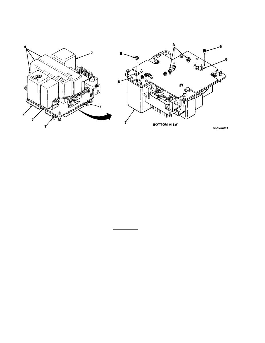
2-20. A5000 MODULE AND ASSEMBLY REPLACEMENT. (CONT)
REMOVAL (CONT)
5.
Pull out four slide clips (1) and remove shield (2).
NOTE
Modules A5100 through A5300 are secured with captive screws. Steps 6 and 7 are
typical for all modules.
Using screwdriver, loosen captive screws (3).
6.
7.
Carefully pull module (4) off board to release from pins. Do not twist from side to side.
NOTE
Modules FL5001 and T5001 are secured with locknuts and are soldered to printed circuit
board. Steps 8, 9, and 10 are typical for both modules.
8.
Using wrench, remove locknuts (5).
CAUTION
Care must be taken when performing next step to prevent damage to printed circuit
board.
9.
10.
Carefully pull modules (7) off board.
2-42
|
|
Privacy Statement - Press Release - Copyright Information. - Contact Us |
