 |
|||
|
|
|||
|
|
|||
| ||||||||||
|
|  TM 11-5820-401-34-3/0967-LP-432-3060
2-19. A4000 MODULE AND ASSEMBLY REPLACEMENT. (CONT)
REMOVAL (CONT)
NOTE
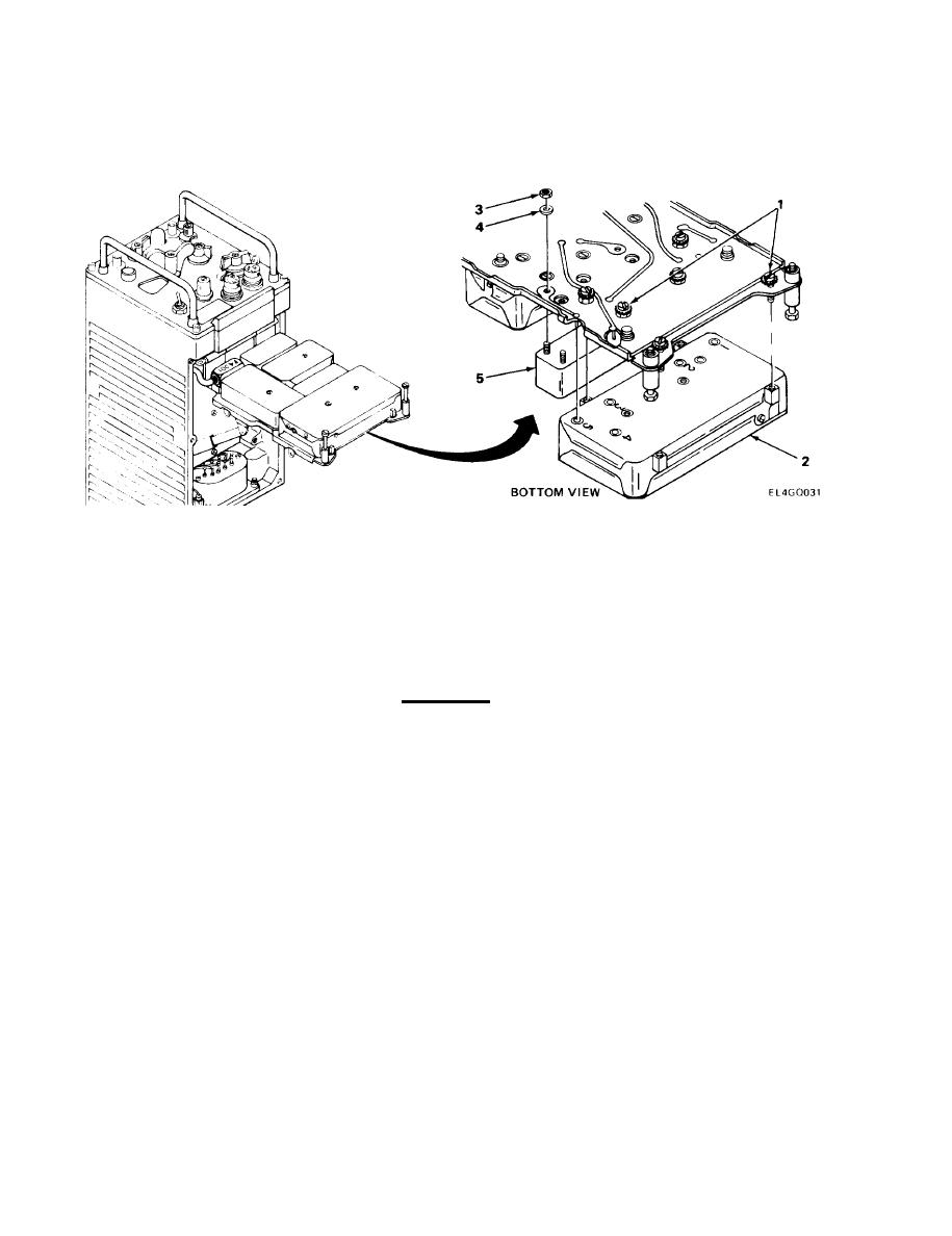
Modules A4100 through A4300 are secured with captive screws. Steps 4 and 5 are typi-
cal for all modules.
4. Using screwdriver, loosen captive screws (1).
5. Carefully pull module (2) off board to release from pins. Do not twist from side to side.
CAUTION
Extreme care must be taken when performing next step to prevent damaging test points
on printed circuit board.
NOTE
Modules FL4001 and FL4002 are secured with locknuts. Steps 6 and 7 are typical for
both modules.
Note position of FL4002 module for 50KC or WIDE BAND operation mode.
6. Using wrench, remove locknuts (3) and IT Iockwashers (4).
7. Carefully pull module (5) off board.
2-36
|
|
Privacy Statement - Press Release - Copyright Information. - Contact Us |
