 |
|||
|
|
|||
|
Page Title:
Isolating Trouble in Module A21 |
|
||
| ||||||||||
|
| 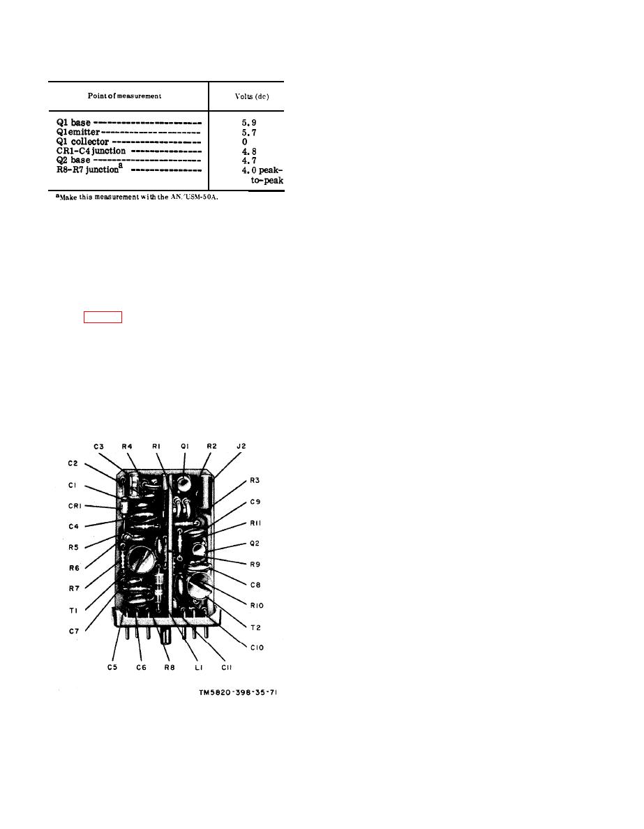 (b) DC voltage chart.
(f) Handset H-138/U.
(h) Multimeter ME-26B/U.
(2) Remove module A5.
(3) Connect the H-138/U to an AUDIO
connector.
(4) Set
the
receiver-transmitter
function switch at ON.
(5) Connect the AN/URM-43A to ANT
connector J2.
(6) Connect the AN/URM-48 output to
the AN/USM-26. Adjust the AN/
U R M - 4 8 frequency to 11.500
(4) After replacing a faulty part, re-
mc, as indicated by the AN/USM-
peat the procedures given in b, c,
26.
and d above.
(5) Replace module A23. Remove the
(7) Disconnect the AN/URM-48 from
module extender.
the AN/USM-26 and connect it be-
tween pins C and D of J9 (receptacle
for A5).
(8) Frequency modulate the AN/URM-
48 with a 1,000-cps sinusoidal sig-
a. Preparation.
nal at a deviation of 10 kc peak.
(1) Prepare the following equipment:
b. Gain Test.
(1) Connect the 411A across the output
(b) Frequency Meter AN/USM-26.
of the AN/URM-48.
(c) Voltmeter, Meter ME-30A/U.
(2) Adjust the level of the AN/URM-
48 to obtain a l-millivolt indication
(e) Spectrum Analyzer TS-723A/U.
on the 411A.
(3) Connect the ME-26/U between
A25J4 and ground.
(4) Adjust the receiver-transmitter
VOLUME control to obtain a 1.0-
volt indication on the ME-26/U.
(5) Connect the ME-30A/U between
A25J3 and ground. The ME-30A/U
should indicate between 180 and
360 millivolts. Record the voltage.
(6) Decrease the AN/URM-48 level
until the ME-30A/U indication de-
creases 3 db from the level noted
in (5) above.
(7) The AN/URM-48 output 1 e v e 1
across pins C and D of J9 should
be between 2.5 and 5.0 microvolt
rms.
(8) If the results given in (1) through
(7) above are not obtained, proceed
toe below.
c. Bandwidth Test.
(1) Repeat the procedures given in a(1)
through (8) above.
(2) Connect the 411A between the case
of Q4 and ground.
Figure 72. Module A20, parts location.
|
|
Privacy Statement - Press Release - Copyright Information. - Contact Us |
