 |
|||
|
|
|||
|
Page Title:
Isolating Troubles in Module A20 |
|
||
| ||||||||||
|
|  A20J2 and connect the AN/USM-26
through (12) above as required. Re-
to that point.
lease the push-to-talk switch.
(15) Press the push-to-talk switch.
(14) Change the receiver-transmitter
(16) The AN/USM-26 should indicate
BAND switch from 30-52 to 53-75.
11.5485 mc 300 cps.
(15) Press and hold the push-to-talk
(17) Release the push-to-talk switch.
switch. Repeat the procedures
(18) If the indications obtained in the
given in (8) above if required.
procedure given in (5), (6), (9),
(16) Adjust C1 for a minimum indication
(120), and (16) above are not nor-
on the ME-57/U.
(17) Adjust C2 until the AN/USM-26 in-
mal, proceed to the alignment
procedures in c below. (Do not dis -
dicates 11.5485 mc 300 cps.
(18) Adjust L1 until the ME-57/U indi-
turb equipment settings or con-
nections.)
cates a 10 kc 2 deviation.
(19) Readjust C1 to obtain a minimum
(19) If the indications obtained above
distortion indication on the TS-
are normal, the A19 testing is com-
723A/U.
pleted.
(20) Repeat the procedures given in (17)
c. Alignment Procedure.
through (20) above as required. Re-
(1) Remove module A23.
lease the push-to-talk switch.
(2) Connect the TS-382F/U between
pin D of an AUDIO connector and
d. Faulty Part Isolation.
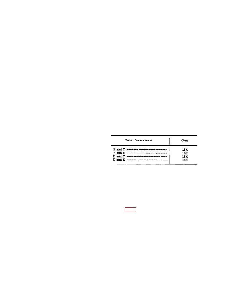
(1) Remove module A19.
ground. Connect the ME-30A/U
(2) Make resistance checks, using the
across the TS-382 F/U output.
(3) Adjust the TS-382F/U frequency to
ME-26B/U, between the pins of J1
on A19 listed in the chart below:
1 kc and the level to 1.4 millivolts,
as indicated by the ME-30A/U.
(4) Connect the ME-57/U across the
AN/USM-26 input through a UG-
274B/U.
(5) Connect the TS-723A/U to the
AUDIO OUTPUT connector of the
ME-57/U.
(6) Connect the AN/USM-50A between
(3) Check crystals A19Y1 and A19Y2
A22J3 and chassis ground.
by substitution.
(7) T u r n the receiver-transmitter
(4) After replacing a faulty part, re-
BAND switch to 30-52. Press and
place module A19 and repeat the
hold the push-to-talk switch.
procedures given in b and c above.
(8) Adjust the output level of the TS-
Replace module A23,
382 F/U to obtain a 5-volt peak-to-
peak presentation on the AN/USM-
50A. If clipping is observed, slowly
decrease the TS-382F/U output
level until the wave becomes sinus-
oidal.
a. Preparation.
(9) Adjust C4 for a minimum indication
(1) Prepare the following equipment:
on the ME-57/U.
(10) Adjust C5 until the AN/USM-26 in-
(b) Frequency Meter AN/USM-26.
dicates 11.4485 mc 300 cps.
(c) Meter, Modulation ME-57/U.
(11) Adjust L2 until the ME-57/U indi-
cates a 10 kc 2 deviation.
(12) Readjust C4 to obtain a maximum
(f) Oscilloscope AN/USM-50A.
distortion indication on the TS-
723A/U.
(h) Module extender.
(13) Repeat the procedures given in (10)
(2) Re move modules A20 and A23.
|
|
Privacy Statement - Press Release - Copyright Information. - Contact Us |
