 |
|||
|
|
|||
|
|
|||
| ||||||||||
|
|  noted in (3) above. Record the fre-
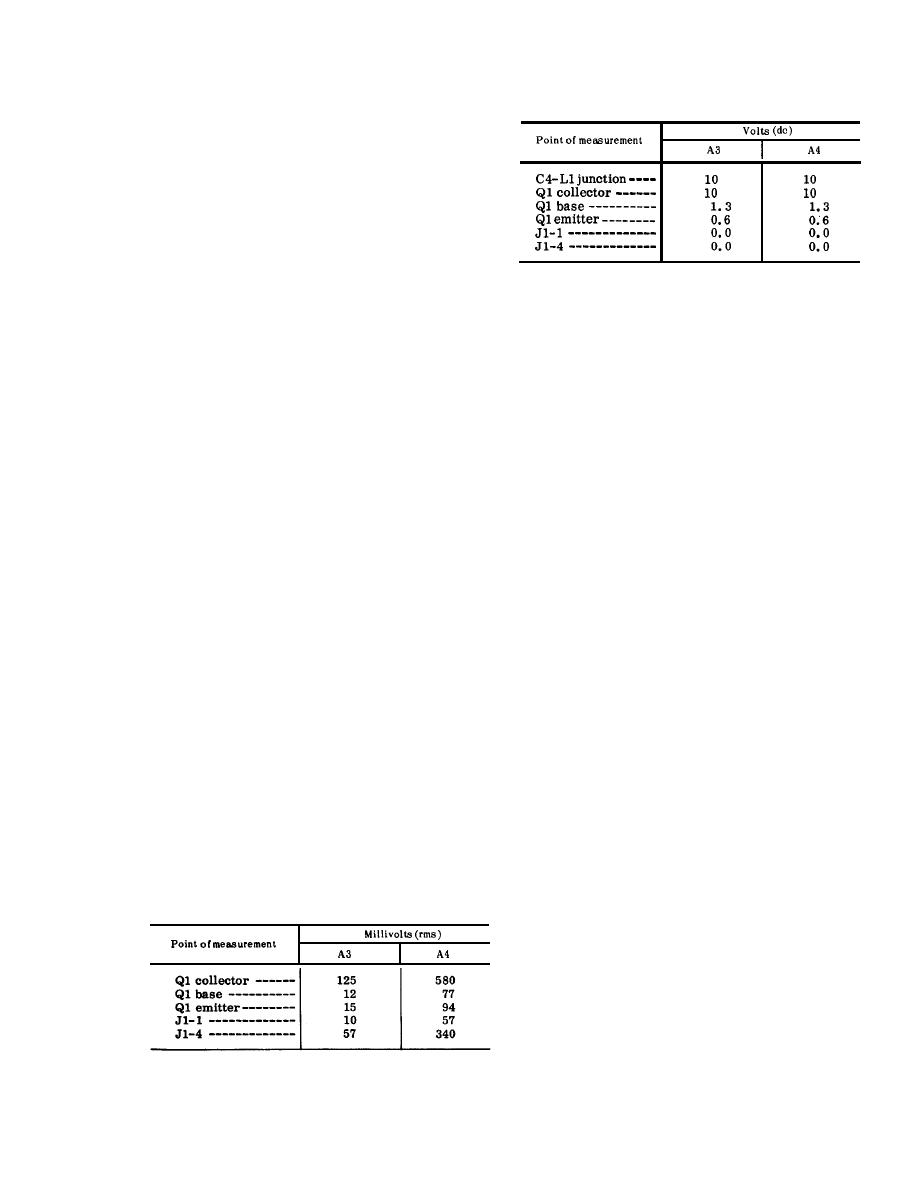
(b) Dc voltage chart.
quency.
(9) I n c r e a s e the AN/URM-48 fre-
quency until the output level indi-
cated by the 411A is again at the
level noted in (3) above. Record
the frequency.
(10) Compute the difference between
the frequencies noted in (8) and (9)
above. The frequency difference
(2) After the replacement of a faulty
is the 6-db bandwidth, which should
..
part, perform the alignment pro:
be 700 kc.
cedure given in d and e below and
(11) Repeat the procedures given in (1)
repeat the procedures given in a
through (10) above for A3 at 52.95
and b above.
mc, 53.00 mc, and 75.95 mc. The
gain noted in (4) above should be
d. Preparation for Alignment.
(1) Set the receiver-tansmitter front
14 db, 12 db, and 12 db respectively.
panel controls as follows:
The bandwidth computed in the pro-
(a) Set the BAND switch and the tun-
cedures given in (10) above should
ing knobs at the AN/URM-48 fre-
be 2,000 kc, 2,500 kc, and 6,700 kc,
quency.
respectively.
(b) Set the function switch at ON.
(12) Repeat the procedures given in (1)
(c) Remove A5.
through (10) above for A4 at 30.00
(2) Connect a shorting jumper between
mc, 52.95 mc, 53.00 mc, and 75.95
mc. The gain noted in (4) above
pins E and H of J9 (receptacle for
should be 13.5 db, 19 db, 15 db,
A5) .
and 13.5 db respectively. The band-
e. Alignment Procedures.
width computed in (10) above should
(1) Adjust the AN/URM-48 output fre-
be 700 kc, 1,200 kc, 1,600 kc, and
quency to 30.00 mc. Connect the
3,100 kc respectively.
411A between pin B of J9 and
(13) If either the gain or bandwidth tests
ground.
or both do not meet the outlined
(2) Tune transformer T2 for a peak
standards of the procedure, pro-
indication on the 411A.
ceed to d and e below.
(3) Change the AN/URM-48 frequency
c. Faulty Parts Isolation.
to 52.00 mc.
(1) Apply a 30.00 mc signal to the
(4) Tune capacitor C7 for a peak indi-
r e c e i v e r - t r a n s m i t t e r ANT con-
cation on the 411A.
nector, adjusted to 10 millivolts
(5) Repeat the procedures give n in
at test point J2 of A3. Measure
(1) through (4) above until the 411A
the voltages at the points outlined
indication for 30.00 mc and
below. Compare them with the
52.00 mc cannot be increased by
normal signal and dc voltages
tuning.
listed.
(6) Adjust the AN/URM-48 and the re-
ceiver-transmitter to 53.00 mc.
Note: Measure all voltages to ground.
(7) Tune transformer T3 for a peak
(a) Signal voltage chart.
indication on the 411A.
(8) Change the AN/URM-48 and the
receiver-transmitter frequency to
75.95 mco
(9) Tune capacitor C9 for a peak indi-
cation on the 411A.
(10) Repeat the procedures given in (6)
through (9) above until the 411A
111
|
|
Privacy Statement - Press Release - Copyright Information. - Contact Us |
