 |
|||
|
|
|||
|
Page Title:
Audiofrequency Response Characteristics |
|
||
| ||||||||||
|
|  the second set of measurements with the
with a 1,000-cycle audio signal.
input voltage reduced to 103 (or 207) volts
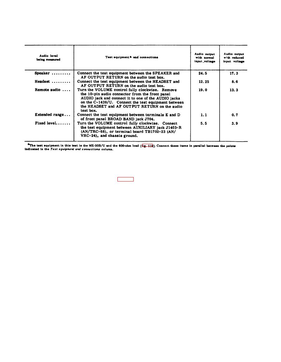
d. To perform the test in the chart below,
ac (AN/TRC-68) or 22 volts dc (AN/VRC-
make one set of measurements with nor-
24) .
mal input voltage applied to the rt unit and
and 10,000 cps and, without further adjust-
ment of the rt unit controls, measure and
Characteristics
record the db indication of the ME-30B/U.
Connect the AN/VRC-24 or the AN/TRC-
At 300 and 3,000 cps, the audio output
68 to the test equipment as shown in figure
level must be within 2 db of the indication
116. Connect the TS-382A/U to the EXT
in d above. The audio output level at 100,
MOD jack of the TS-497/URR to provide
5,000, and 10,000 cps should be at least
external modulating frequencies from 100
-8 db, -5 db, and -20 db respectively from
to 25,000 cps. Do not connect the TS-723A/
the indication in d above.
f. Connect the 600-ohm load and ME-
U or the AN /URM-25D.
30B/U between the HEADSET and AF OUT-
a. Tune the rt unit and TS-497/URR to
PUT RETURN terminals of the audio test
any convenient frequency.
b. Adjust the TS-497/URR for a 1,000-
box.
microvolt signal modulated 30 percent with
g. Repeat the audio response measure-
a 1,000-cycle audio signal.
ments made in e above. Do not change the
c. Set the front panel METER switch to
setting of the front panel VOLUME con-
S-METER and adjust the TS-497/URR fre-
trol. Record the db indications. The db re-
quency for a maximum S-METER indica-
lationships must be the same as in e above.
h. Connect the 600-ohm load and ME-
tion.
d. Connect the ME-30B/U and 600-ohm
30B/U between AUXILIARY jack J1403-R
load across the SPEAKER and AF OUTPUT
(AN/TRC-68) or terminal board TB1702-
RETURN terminals of the audio test box
23 (AN/VRC-24), and chassis ground, and
and adjust the front panel VOLUME con-
repeat the measurements made in e above.
trol for 1 watt of audio output power (24.5
Record the db indications. The db relation-
volts rms across the 600-ohm load). Re-
ships must be the same as in e above.
i. Disconnect the audio test box from the
cord the corresponding db indication of the
ME-30B/U.
front panel AUDIO jack and connect it to
e. Set the TS-382A/U modulation signal
either of the C-1439/U AUDIO jacks. Con-
to frequencies of 100, 300, 3,000, 5,000,
nect the 600-ohm load and the ME-30B/U
|
|
Privacy Statement - Press Release - Copyright Information. - Contact Us |
