 |
|||
|
|
|||
|
|
|||
| ||||||||||
|
|  Section III. ALIGNMENT
Required
itate the connection of test equipment such
as voltmeters and signal generators to the
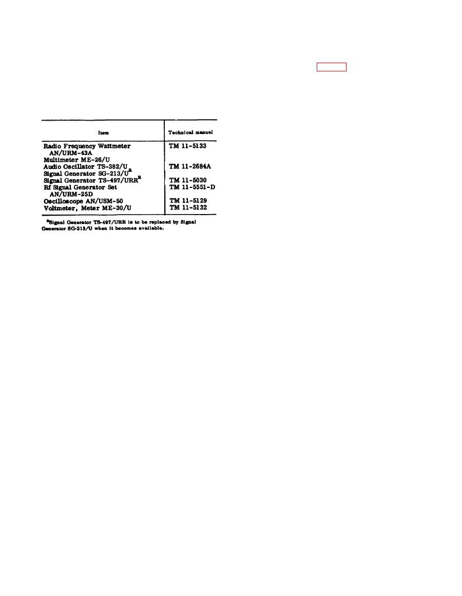
a. Test Equipment. The following test
10-pin AUDIO jacks, prepare an audio
equipment is required for alignment of
t e s t box. The materials required are a
Radio Sets AN/VRC-24 and AN/TRC-68.
small metal or wooden chassis, a spare
10-pin audio connector, six test terminals
or jacks, six 2-foot lengths of No. 22 cop-
per wire, and a 2-foot length of No. 22 or
No. 26 shielded wire. Mount the test ter-
minals on the chassis. Connect, solder, and
label the test terminals to the 10-pin audio
connector as follows:
(1) Connect one end of a length of the
No. 22 copper wire to pin L of the
10-pin audio connector, and label
the other end SPEAKER.
(2) Connect one end of a length of the
No. 22 copper wire to pin B of the
10-pin audio connector, and label
b. Special Tools. The following special
the other end AF OUTPUT RE-
tools are required for alignment.
TURN.
(1) Alignment tool. This tool (Federal
(3) Connect one end of a length of the
s t o c k No. 5120-690-7403) is a
No. 22 copper wire to pin E of the
phenolic, lucite, or nylon rod 3/16
10-pin audio connector, and label
i n c h in diameter, with a screw-
the other end AF INPUT RETURN.
driver blade on one end and a slot
(4) Connect one end of a length of the
on the other end. It is used for coil
No. 22 copper wire to pin H of the
slug and trimmer capacitor adjust-
10-pin audio connector, and label
ments.
t h e other end CONT LINE RE-
(2) T a b - b e n d i n g tool. This tool is a
TURN.
lucite rod with a pointed end. It is
(5) Connect one end of a length of the
used to bend the tabs on the tuning
No. 22 copper wire to pin A of the
capacitors.
10-pin audio connector, and label
(3) T u n i n g wand. The tuning wand
the other end HEADSET.
(Federal stock No. 5120-521-8775)
(6) Connect one end of the shielded
is a phenolic, lucite, or nylon rod
wire to pin C of the 10-pin audio
w i t h a 3/16-inch diamater brass
connector, and label the other end
slug on one end and a 3/16-inch
AF INPUT. Ground the shield to
diameter powdered iron slug on the
pin B of the 10-pin audio connector.
other end. It is used to check the
(7) Connect one end of a length of the
alignment of tuning coils. When the
No. 22 copper wire to pin F of the
brass slug is inserted into a coil,
10-pin audio connector, and label
the inductance is decreased and the
the other end RADIO CONT LINE.
resonant frequency of the tuned
circuit is raised. When the pow-
dered iron slug is inserted into a
coil, the inductance is increased
a. General. The following paragraphs
and the resonant frequency of the
contain alignment and adjustment pro-
tuned circuit is lowered.
c e d u r e s necessary to obtain optimum
|
|
Privacy Statement - Press Release - Copyright Information. - Contact Us |
