 |
|||
|
|
|||
|
Page Title:
Removal and Replacement of Uhf Capacitor Tuning Shaft |
|
||
| ||||||||||
|
|  TM5820-222-35-92
cover plate removed.
b. Replacement.
(1) Reseat the frequency multiplier-
Capacitor Tuning Shaft
amplifier assembly on the uhf in-
a. Removal.
jection subunit and align the screw
(1) Remove the uhf injection subunit
h o l e s . Replace the 12 retaining
from the rt unit main frame (para
screws (1, fig. 93).
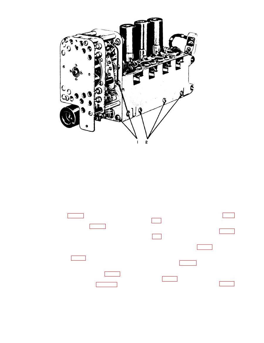
(2) Resolder the capacitor leads to the
(2) Index the tuning capacitor shaft and
junctions marked 2 (fig. 90).
crystal
switching
Caution: Do not place any strain
on the variable capacitor tabs. Sol-
(3) Remove the five retaining screws
der carefully; do not overheat.
and flat washers (2, fig. 92 and 91).
Slip the cover plate off the chassis.
(3) Connect and resolder the lead to the
(4) Remove the two spring-retaining
junction (1, fig. 90).
screws (1, fig. 94). Remove the
(4) Replace the cover plate and replace
spring.
t h e retaining screws marked 3;
(5) Slide the three grounding fingers
tighten the two screws (2, fig. 92).
(2, fig. 94) off the casting.
(5) Replace the uhf injection subunit in
(6) Remove the three screws (2, fig.
the rt unit mainframe (para 108b).
|
|
Privacy Statement - Press Release - Copyright Information. - Contact Us |
