 |
|||
|
|
|||
|
|
|||
| ||||||||||
|
|  TB 9-2320-387-35-3
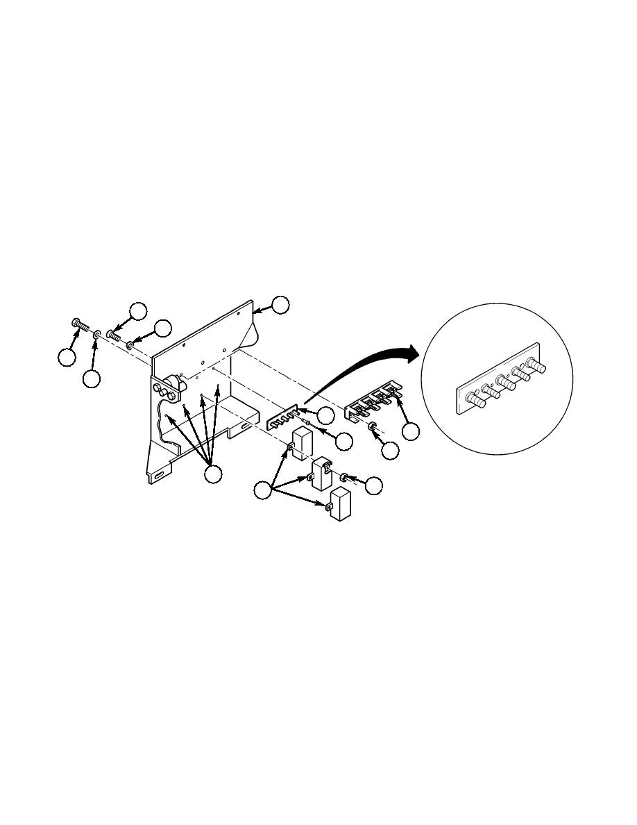
5-4. Install 24V terminal board (10) on enclosure panel (7) with three screws (2), three lockwashers (3),
and three nuts (5).
5-5. Enlarge two holes marked A in terminal board (8) to 0.196 in. and secure terminal board (8) to
enclosure panel (7) with two rivets (9).
5-6. Install three existing relays (12) in holes (13) on enclosure panel (7) with four existing screws (15),
four washers (14), and four locknuts (11).
7
2
3
15
A
14
A
8
10
9
5
13
11
12
2.
SCREW MS35206-230 QTY. 3
3.
LOCKWASHER MS35338-41 QTY. 3
5.
NUT MS35649-63 QTY. 3
8.
TERMINAL BOARD 12480570 QTY. 1
9.
BLIND RIVET 12339355-1 QTY. 2
11.
LOCKNUT MS51943-31 QTY. 4
Figure 5-9.
5-7
|
|
Privacy Statement - Press Release - Copyright Information. - Contact Us |
