 |
|||
|
|
|||
|
Page Title:
Section XVIII. PLGR BRACKET INSTALLATION |
|
||
| ||||||||||
|
|  TB 9-2320-280-35-7
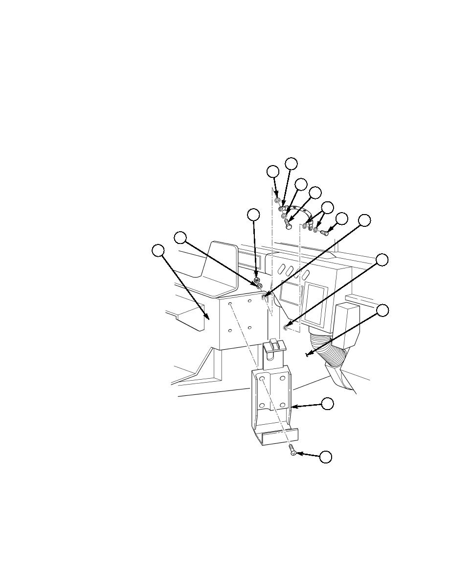
Section XVIII. PLGR BRACKET INSTALLATION
18-1. Install PLGR bracket (11) on integrated rack (1) with four screws (12).
18-2. Locate, mark, and drill one 0.201-in. diameter hole (9) in right-side engine tunnel (10).
18-3. Remove paint from vicinity of hole (8) on integrated rack (1) and hole (9) on right-side engine
tunnel (10). Apply anti-seize compound as required.
18-4. Fabricate ground strap (5) from 8.00-in. length of braided wire and two terminal lugs.
18-5. Install ground strap (5) on integrated rack (1) with capscrew (6), two lockwashers (4), lockwasher
(2), and nut (3).
18-6. Install ground strap (5) on right-side engine tunnel (10) with self-tapping screw (7) and two
lockwashers (4).
5
4
4
6
4
3
7
8
2
1
9
10
~
11
2.
LOCKWASHER MS35338-44 QTY. 1
3.
NUT 9419143 QTY. 1
12
4.
LOCKWASHER MS45904-68 QTY. 4
5.
GROUND STRAP
BRAIDED WIRE AA59569F30T0375 QTY. A/R
TERMINAL LUG MS20659-129 QTY. 2
6.
CAPSCREW B1821BH025C100N QTY. 1
7.
SELF-TAPPING SCREW 9426241 QTY. 1
11.
PLGR BRACKET 986-0645-001 QTY. 1
12.
SCREW MS35206-263 QTY. 4
Figure 5-44.
|
|
Privacy Statement - Press Release - Copyright Information. - Contact Us |
