 |
|||
|
|
|||
|
Page Title:
CHAPTER 5. INSTALLATION PROCEDURES |
|
||
| ||||||||||
|
|  TB 9-2320-280-35-4
INSTALLATION PROCEDURES
Section I. SCOPE
This chapter provides instructions for installation of the following C4ISR equipment:
Single Channel Ground and Airborne Radio System (SINCGARS)
Force XXI Battle Command, Brigade-and-Below (FBCB2)
Frequency-Hopping Multiplexer (FHMUX)
Precision Lightweight Global Positioning System Receiver (PLGR)
Enhanced Position Location Reporting System (EPLRS)
Driver's Vision Enhancer (DVE)
Additional terminal boards in the vehicle
When installing C4ISR equipment, be sure to read and follow instructions and illustrations carefully.
Section II. INSTALLATION OF TERMINAL BOARDS
Use the following procedure to install additional terminal boards to provide adequate power connections.
Vehicles must have dual-voltage alternators installed in order to have 12V and 24V terminal boards
installed.
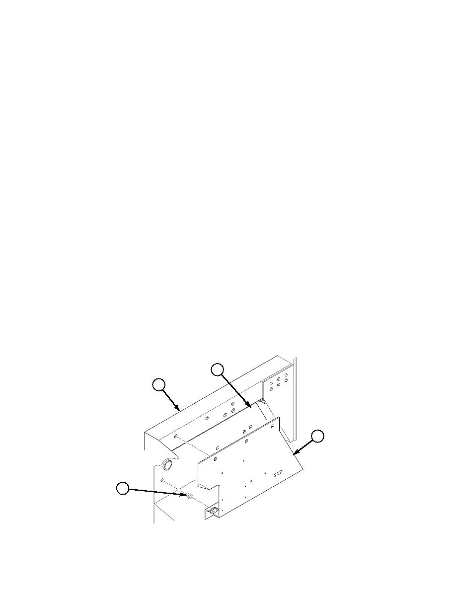
Section III. CAB ENCLOSURE PANEL, TERMINAL BOARD, AND COVER MODIFICATION
NOTE
For vehicles without cab enclosure panel, begin with step 3-1
and use cab enclosure panel NSN 2510-01-413-5993.
For vehicles with cab enclosure panel, begin with step 3-3.
All dimensions are in inches.
3-1. Place cab enclosure panel (3) in position. Locate, mark, and drill five 0.159-in. diameter holes
marked A and B in B-beam (1) and battery box (2).
3-2. Enlarge two lower mounting holes marked A to 0.390-in. diameter, and install two inserts (4) in
battery box (2).
2
1
B
~
B
B
3
A
A
4
3. ENCLOSURE PANEL 12447141 QTY. 1
4. INSERT 12446871-2 QTY. 2
Figure 5-1.
|
|
Privacy Statement - Press Release - Copyright Information. - Contact Us |
