 |
|||
|
|
|||
|
|
|||
| ||||||||||
|
|  TB 9-2320-280-35-3
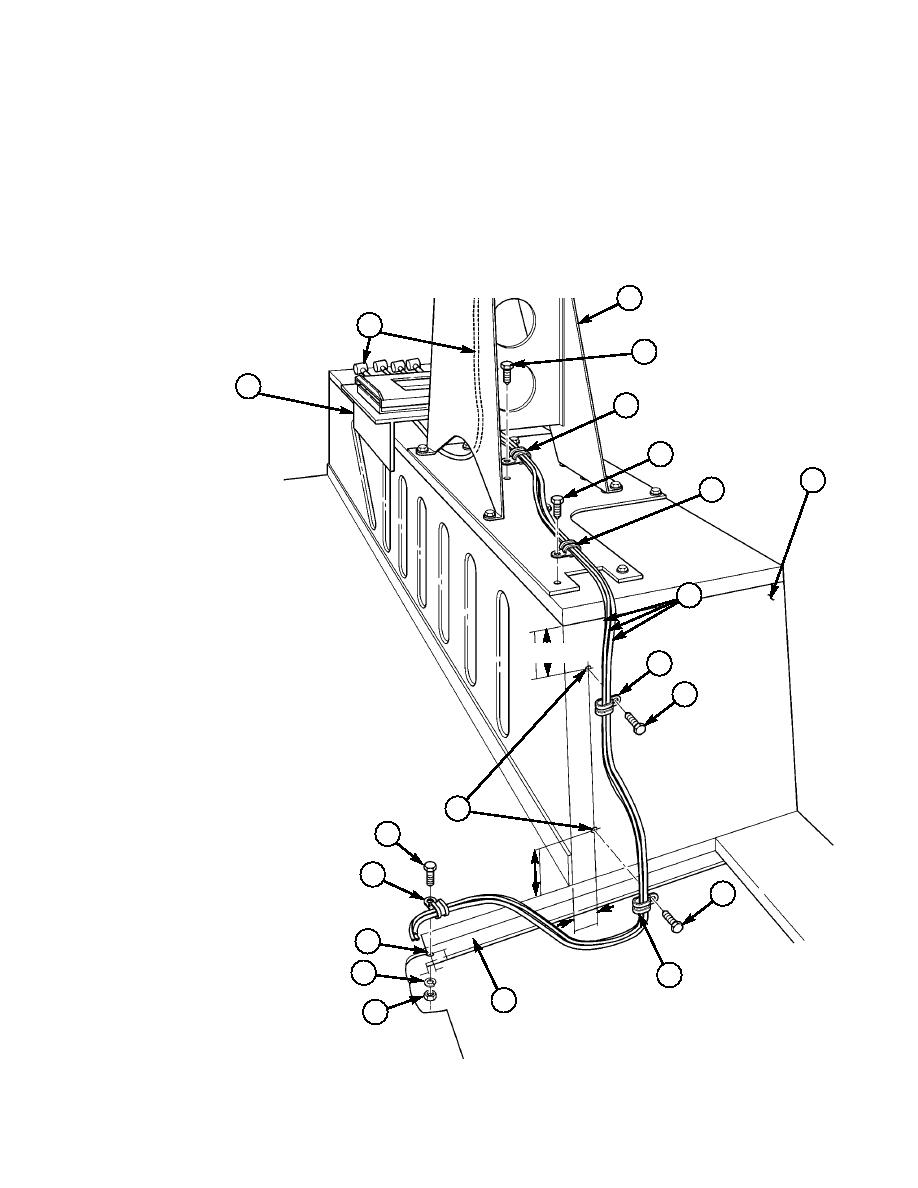
19-14. Locate, mark, and drill one 0.219-in. hole (39) in inboard corner on rear inside lip of left rear seat
back support (36).
19-15. Locate, mark, and drill two 0.147-in. holes (41) in front face of left rear wheelhouse (35).
19-16. Route all cables (34) along rear perimeter of left rear seat back support (36), up front face of left
rear wheelhouse (35), and under antenna base (32) and EPLRS mount assembly (30).
19-17. Secure all cables (34) with screw (40), lockwasher (38), nut (37), two self-tapping screws (23), two
existing screws (33), and five loop clamps (24).
antenna base (32).
32
31
33
30
24
33
35
24
34
2.00
24
23.
SELF-TAPPING SCREW 9421073 QTY. 2
24.
LOOP CLAMP MS21333-77 QTY. 5
23
31.
EPLRS ANTENNA CABLE SM-C-911480 QTY. 1
37.
NUT, PLAIN-ASSEMBLED 9422771 QTY. 1
38.
LOCKWASHER MS35338-43 QTY. 1
40.
SCREW MS35206-265 QTY. 1
41
40
24
2.00
23
2.00
~
39
38
24
36
37
Figure 5-61.
5-49
|
|
Privacy Statement - Press Release - Copyright Information. - Contact Us |
