 |
|||
|
|
|||
|
|
|||
| ||||||||||
|
|  TB 9-2320-280-35-1
NOTE
Perform steps 13-24 through 13-30 for AN/VRC-88F, 89F, 90F, or
91F only.
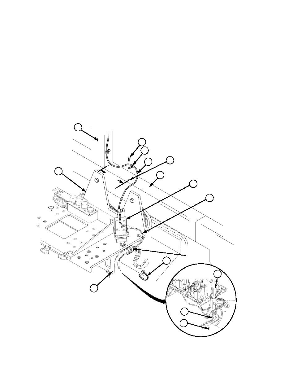
13-24. Locate, mark, and drill 0.147-in. hole (39) in top of dash (30).
13-25. Route antenna cable (9) from windshield center post (28) to PLGR bracket assembly (36) and secure
to front dash (30) with self-tapping screw (25) and loop clamp (26).
13-26. Route PLGR power cable (35) along side of standard rack (38) and secure with existing clamp and
hardware.
13-27. Route PLGR power cable (35) down standard rack support (41) and secure with tiedown strap (40).
13-28. Loosen right side tunnel insulation (37). (Refer to TM 9-2320-280-20 or TM 9-2320-387-24.)
13-29. Route PLGR power cable (35) from standard rack support (41) rearward under right side tunnel
insulation (37) towards B-beam and cab enclosure panel.
13-30. Coil excess antenna cable and store under standard rack (38) using tiedown strap (40) as necessary.
28
25
26
39
9
38
6.0
30
0
36
~
35
EXISTING
CLAMP
40
41
~
41
25. SELF-TAPPING SCREW 9421073 QTY. 1
35
26. LOOP CLAMP MS21333-65 QTY.1
40. TIEDOWN STRAP MS3367-1-0 QTY. A/R
37
Figure 5-40.
5-33
|
|
Privacy Statement - Press Release - Copyright Information. - Contact Us |
