 |
|||
|
|
|||
|
Page Title:
Section VI. FINAL ASSEMBLY, TERMINAL BOARD WIRING, AND TERMINAL LINK |
|
||
| ||||||||||
|
|  TB 9-2320-280-35-1
Section VI. FINAL ASSEMBLY, TERMINAL BOARD WIRING, AND TERMINAL LINK
NOTE
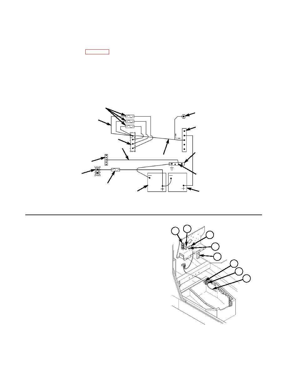
Refer to figure 5-9 for wiring overview.
Perform steps 6-1 and 6-2 if hole and grommet do not exist in
battery box.
6-1. Locate, mark, and drill 2.00-in. diameter hole (6) in upper right corner of rear wall of battery box.
6-2. Install grommet (7) in hole (6).
6-3. Secure terminal link (2) and fuse wire (3) to 12V terminal board (1) with two locknuts (4), and
install cover (5).
6-4. Route wire (8) through battery box hole (6).
3 X 24V FUSES, 25 AMP
EXISTING VEHICLE POWER STUD
POSITIVE FUSE WIRES
EXISTING VEHICLE BUSS BAR
24V BUSS BAR
GROUND WIRE
EXISTING VEHICLE SHUNT
POWER WIRE
GROUND STRAP
12V BUSS BAR
GROUND SCREW
12V FUSE, 15 AMP
VEHICLE BATTERY
VEHICLE
BATTERY
2
1
3
4
5
6
7
8
2.
TERMINAL LINK MS25226-6N-2 QTY. 1
3.
FUSE WIRE ASSEMBLY (12V) 12480568-2 QTY. 1
4.
LOCKNUT 271175 QTY. 2
5.
TERMINAL BOARD COVER MS18029-3S-2 QTY. 1
7.
GROMMET 2400 QTY. 1
Figure 5-10.
|
|
Privacy Statement - Press Release - Copyright Information. - Contact Us |
