 |
|||
|
|
|||
|
|
|||
| ||||||||||
|
|  TB 11-5820-890-10-11
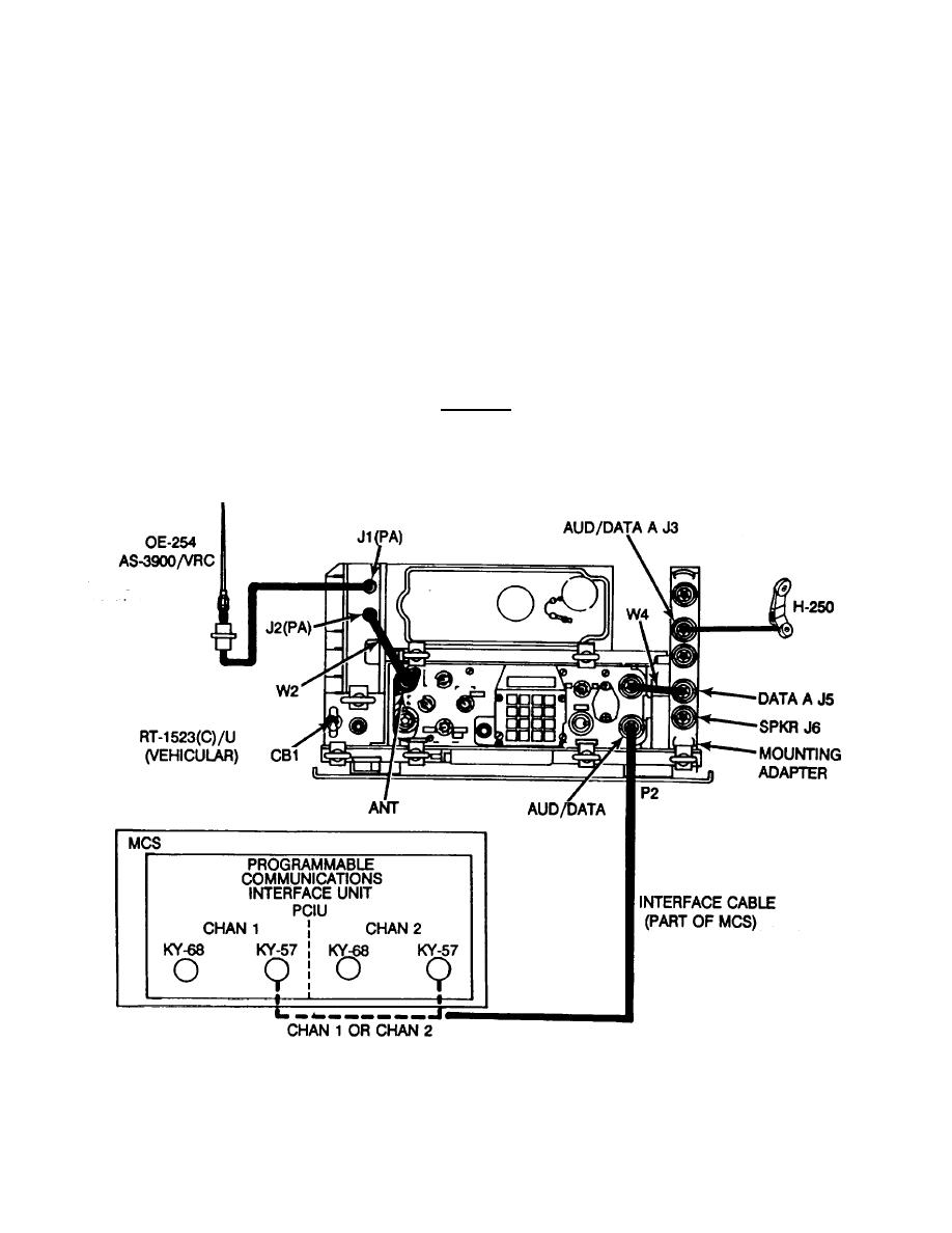
5. Cable Instructions. The following figure illustrates the typical configuration for the connection between the radio
set and the MCS.
Connect MCS Interface cable from PCIU KY-57 connector to RT AUD/DATA connector. DO NOT
connect interface cable to mounting adapter.
Connect W4 cable from RT AUD/FILL to J5 on mounting adapter.
Connect handset H-250/U to mounting adapter J3 (AUD/DATA) connector.
Make sure that MCS and the RT (in vehicular mount) are grounded (on parallel) to each other.
Figure shows the MCS connected to lower radio (RT-A).
MCS may be connected to upper radio (RT-B) if desired.
CAUTION
DO NOT CONNECT INTERFACE CABLE TO PCIU KY48 CONNECTOR AS EQUIPMENT DAMAGE MAY RESULT.
NOTE
THE RT MAY BE MOUNTED IN A VEHICULAR MOUNT OR IN A MANPACK. THE INTERFACE CABLE IS
CONNECTED TO RT AUD/DATA CONNECTOR FOR BOTH CONFIGURATIONS.
Figure 1. Cabling for MCS to SINCGARS Radio Set
2
|
|
Privacy Statement - Press Release - Copyright Information. - Contact Us |
