 |
|||
|
|
|||
|
|
|||
| ||||||||||
|
|  supply, Component designations in the following paragraphs refer to
the schematic diagram, Figure 4-7.
3.2.2 STROBOTRON TUBE.
In most modern stroboscopes, the flash occurs inside a xenon-filled
tube. The gas in the tube is ionized by the rapid discharge of a capacitor.
The gas must then deionize before the next flash can occur. This deioni -
zat ion time sets the limit on the maximum flashing rate of the instrument.
If too high a voltage is applied across the tube before it is deionized, an
erratic condition (continuous conduction) known as "hold-over" will
result.
The strobotron tube contains two main elements, a cathode and an
anode. A discharge capacitor acts as a low impeace source of voltage
across these electrodes, The gas, however, remains non-conducting
(deionized) until a pulse of high voltage is applied to trigger wires inter-
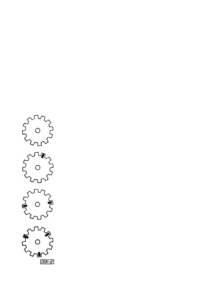
Gear not marked for speed measurement. Simple
observation is possible but observer cannot be
certain if image is single or multiple.
Single image observed with tape applied to one tooth
of gear.
Multiple (double) image observed with tape applied
to one tooth of gear. Images are 180 apart,
Multiple (triple) image observed with tape applied
to one tooth of gear. Images are 120 apart.
Single and multiple images of a rotating gear as
observed with o stroboscope.
21
|
|
Privacy Statement - Press Release - Copyright Information. - Contact Us |
