 |
|||
|
|
|||
|
Page Title:
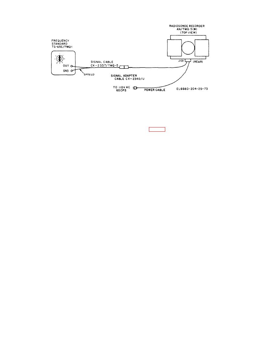
Figure 8-1. External test configuration. |
|
||
| ||||||||||
|
|  TM 11-6660-204-25
(4) Repeat steps (1), (2), and (3) above to
8-7. Pen-Lift Test
insure that one adjustment has not altered an-
other.
(5) Turn the SIGNAL SELECTOR switch to
Test Set TS-65C/FMQ-1 to 190 Hz at a peak-to-
SIG. position.
peak voltage of 10 volts. Remove the screws from
c. Mechanical Checks. Perform the following
the converter panel and pull down the panel door
visual checks prior to equipment warmup:
to obtain access to the test jacks. Connect Oscillo-
( 1 ) All mechanical components including
scope AN/USM-140A to the output of Test Set
panel locks and rack slides should operate
TS-65C. Connect the signal lead of the test cable
smoothly.
from the output of the test set to jack J303 and
(2) The frequency-time recorder chart drive
the shield of the cable to ground at jack J326.
gear train shall have no worn gears or broken
b. Operate the SIGNAL SELECTOR switch to
gear teeth. All chart drive gear train mechanism
the SIG. position and adjust the test set so the
mounting components shall be secure.
recorder pen will print successively at approxi-
d. Powerline Frequency and Voltage Meters.
mately 0, 30, 60, 95, 60, 30, and 0 chart divisions.
The powerline frequency meter should indicate 60
c. The beginning and ending tails of
Hz. The powerline voltage meter should indicate
the recording shall not exceed two chart
within 5% of the input line voltage from the
recorder divisions.
power source.
8-5. Fan Operation
d. Replace the screws and secure the control
a. Place a piece of tissue paper over the fan
panel unless other tests are to be made.
opening. The fan will have sufficient air moving
capabilities if the paper remains in place while
8-8. Chatter
the fan is in operation.
a. Place SIGNAL SELECTOR switch in S.C.
b. Remove the tissue paper from the fan open-
position, allow pen to print at 0 chart divisions
ing.
for a few seconds, depress REC. TEST switch and
hold until the pen comes to rest, then release and
8-6. Speaker Output
allow the pen to return to 0 chart divisions.
The speaker output test will be conducted simulta-
b. There should be no chatter of the pen holder
neously with the pen tests at various frequencies.
assembly when moving either up or down scale.
During these tests, listen to the speaker output
and signal quality; it should be free of audible
8-9. Pen Pressure
distortion and be capable of being heard in a rea-
a. Place the control panel power switch in the
sonably quiet room at a distance of 25 feet.
Change 2
|
|
Privacy Statement - Press Release - Copyright Information. - Contact Us |
