 |
|||
|
|
|||
|
|
|||
| ||||||||||
|
|  TM 11-6625-924-14
b. Align O degree on the indicator heading dial with
TESTS switch to the ALL OTHER TESTS position.
the major index.
b. Adjust the 1.5V ADJ control for 1.5 vac as
measured across the 1.5V binding posts.
c. Set the synchro transmitter No. 2 control to the 0
degree position.
C. Connect the ME-30A/U across the VTVM binding
posts.
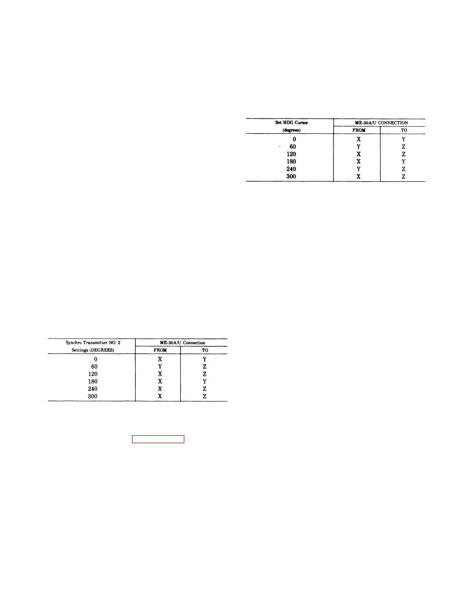
d. Rotate the indicator Set HDG control for a null on
the ME-30A/U at each position of the Set HDG Cursor
d. Rotate the indicator SYNC knob until its heading
listed in the following chart. The Set HDG Cursor
dial aligns with the major index.
should be within 0.5 degree when null is obtained.
e. Rotate synchro transmitter No. 1 control for a
null on the ME-30A/U.
degree.
g. Rotate the synchro transmitter No. 2 control and
the synchro transmitter No. 1 control in 60-degree in-
crements and adjust the synchro transmitter No. 1 con-
trol for a null on the ME-30A/U.
h. The error between the synchro transmitter dials
at each reading should not exceed 0.5 degree.
3-14. Flag Test
a. Rotate the BRIDGE SEL switch to the FLAG
3-11. B307 Calibration Error Test
CUR position.
a. Set the B307-B308-B304 switch to the B307 posi-
b. Rotate the CUR ADJ control until the flagon the
tion.
indicator starts to move. The meter should indicate 280
b. Connect the ME-30A/U between the adjacent X
microampere or more (scale X10).
and Y binding posts.
c. Rotate the CUR ADJ control until the flag on the
C. Rotate the synchro transmitter No. 2 control for a
indicator is out of sight and stops. The meter should in-
null on the ME-30A/U.
dicate 430 microampere 30.
d. The synchro transmitter No. 2 dial should indi-
cate 0.5 degree.
3-15. Annunciator Test
e. Rotate the synchro transmitter No. 2 control to
a. Rotate the BRIDGE SEL switch to the ANNUN
each position indicated in the following chart and con-
CUR+ position.
nect the ME-30A/U between the indicated binding
b. Rotate the CUR ADJ control until a dot appears
posts. Adjust the synchro transmitter No. 2 control for
fully in the window of the indicator. The meter should
a null on the ME-30A/U; its dial should indicate within
indicate between 140 and 230 microampere (scale
0.5 degree of the settings indicated in the chart.
Xl0).
c. Rotate the BRIDGE SEL switch to the ANNUN
CUR- position.
d. Rotate the CUR ADJ control until a cross appears
fully in the window of the indicator. The meter should
indicate between 140 and 230 microampere (scale
Xl0).
3 - 1 6 . Stopping Procedures
a. Set the ON-OFF switch to OFF and turn the
3-12. B308 Calibration Error Test
power source off.
a. Rotate the B307-B308-B304 switch to the B308
b. Disconnect the test panel from the power source.
position.
c. Disconnect the indicator from the test panel ca-
ble.
3-13. B304 Calibration Error Test
d. Remove the indicators from the indicator mount
a. Set the B307-B308-B304 switch to the B304 posi-
on the test panel.
tion.
3-3
|
|
Privacy Statement - Press Release - Copyright Information. - Contact Us |
