 |
|||
|
|
|||
|
Page Title:
Figure 95. Test setup for interference measurement. |
|
||
| ||||||||||
|
| 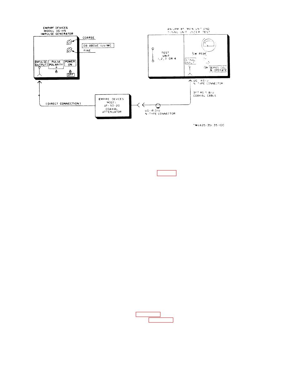 Figure 95. Test setup for interference measurement.
(4) If tuning unit 2, 3, or 4 is installed
b. O n t h e I G - 1 1 5 i m p u l s e g e n e r a t o r ,
in the main unit, rotate the SIGNAL
proceed as follows:
A T T E N U A T O R DB control to 20.
(1) Set the POWER switch to the ON
(5) W i t h the test setup as indicated
position.
( f i g . 95), record the pointer de-
(2) S e t the PULSE POLARITY switch
flection on the panel meter of the
to the + position.
unit under test.
(3) Set the DB ABOVE lV/MC coarse
and fine output level controls to a
t h e POWER switch to OFF.
v a l u e of 20 db greater than the
s e t t i n g s shown in the calibration
e. On the unit under test, perform the
c h a r t s (4A and 4B) supplied with
following procedure:
(1) Set the calibration switch to SHUNT
each test set. The tuning unit and
f r e q u e n c y selected will determine
CAL.
(2) Set the IMPULSE GENERATOR DB
the DB ABOVE lV/MC corase
and fine output level settings. For
ABOVE lV/MC switch to ON.
i n s t a n c e , if the calibration chart
(3) S e t the impulse generator coarse
s h o w s a control setting of 62 db
a n d fine output controls to those
for the frequency selected, set the
settings that produce the same
D B ABOVE lV/MC coarse and
pointer deflection as in c(5) above.
fine output level controls to a value
The settings of the output controls
of 82 db.
m u s t correspond within 1 db of
C . On the unit under test, proceed as
t h e calibration chart control set-
follows:
t i n g shown for the frequency se-
(1) R o t a t e the function switch to the
lected.
CW PEAK position.
(2) S e t t h e t h e c a l i b r a t i o n s w i t c h
105. CW Sensitivity
to SERIES CAL & OPERATE.
a. With a tuning unit plugged into the
(3) If tuning unit 1 is installed in the
m a i n unit, use the same test setup as in
main unit, rotate the SIGNAL AT-
T E N U A T O R DB control to the 0
pad (para 100) for the 5-db variable step
CW ONLY position.
222
|
|
Privacy Statement - Press Release - Copyright Information. - Contact Us |
