 |
|||
|
|
|||
|
Page Title:
Dial Calibration Accuracy |
|
||
| ||||||||||
|
|  (5) Cable, Radio Frequency RG-58/U.
on the meter. If necessary, adjust the
( 6 ) Conneclor, Plug, Electrical UG-
attenuator on the tuning unit signal gener-
1095/U.
ator to keep the reading on scale.
(7) Connector, Male Contact: AN Radio
F r e q u e n c y Plug UG-88/U.
dial. This must be within 2-percent of the
( 8 ) Adapter UG-349/U.
k n o w n accurately calibrated tuning unit
s i g n a l generator frequency.
101. Dial Calibration Accuracy
h. R e p e a t t h e p r o c e d u r e s g i v e n i n d
a. With a tuning unit plugged into the
through g above, increasing the tuning unit
m a i n unit tuning. unit compartment, con-
signal generator frequency in steps of
nect a cable from the rf output jack on the
10-mc.
applicable tuning unit signal generator to
i. R e p e a t t h e p r o c e d u r e s g i v e n i n a
the SIGNAL INPUT jack on the main unit.
through h above with a different frequency
b. set the controls as described in the
r a n g e tuning unit connected in the main
s i g n a l substitution techniques, paragraphs
u n i t , and starting at its lowest frequency
setting. For each tuning unit, the fre-
the tuning unit in use.
q u e n c y dial accuracy must be within 2-
c. Set the function switch to the CW
percent of the tuning signal generator
AVERAGE position.
frequency.
d. Set the band switch (if applicable) and
the TUNING control to the lowest band and
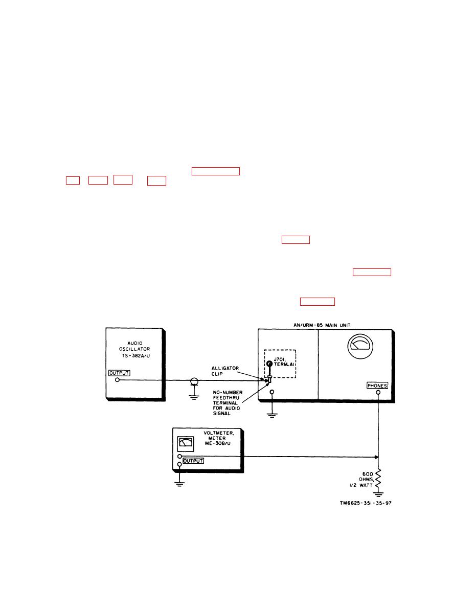
102. Audio Amplifier Response Test
tuning-dial frequency setting. Set the
t u n i n g unit signal generator to the same
T o check the response of audio ampli-
frequency.
f i e r V701 in the main unit, set up the
e. Adjust the attenuator on the tuning
equipment as shown in figure 93 and pro-
unit signal generator to obtain an onscale
ceed as follows:
r e a d i n g on the panel meter of the main
unit.
a. Remove the main unit from its instru-
f. Adjust the TUNING control on the
ment case (para 40b item 12, TM 11-6625-
tuning unit to obtain the maximum reading
351-12).
Figure 93. Test setup for audio amplifier response.
219
|
|
Privacy Statement - Press Release - Copyright Information. - Contact Us |
