 |
|||
|
|
|||
|
|
|||
| ||||||||||
|
| 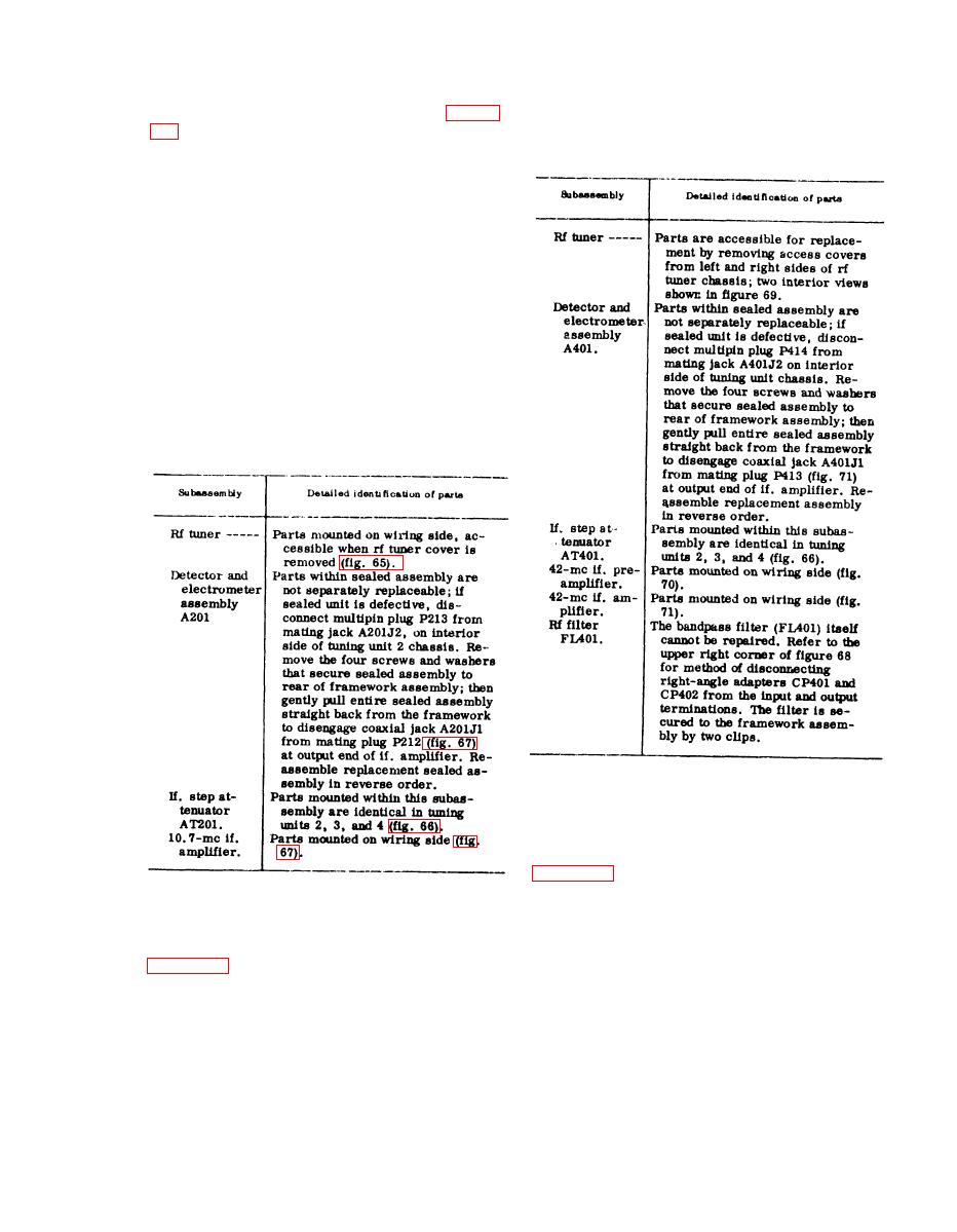 b. Tuning Unit 2. The major subassem-
exploded view illustration for removal and
blies within tuning unit 2, working clock-
reassembly procedures of a defective sub-
a s s e m b l y . Before attempting repairs or
wise from the lower left corner of figure
replacement, refer to the c a u t i o n in b
b e l o w . Identification of the parts within
above.
e a c h subassembly can be determined by
r e f e r r i n g to the individual illustration of
the subassembly. Follow the exploded view
i l l u s t r a t i o n for removal and reassembly
p r o c e d u r e s of a defective subassembly.
Caution: At the higher frequencies re-
ceived by tuning units 2, 3, and 4 (20 to
1,000 mc), the circuits and their wiring
l a y o u t are more critical than in tuning
unit 1. Avoid unnecessary disassembly and
replacement of wiring. Disassembly only
to the extent necessary to repair a defect.
R e s t o r e the layout of the wiring to its
original p o s i t i o n before disassembly,
w h e n e v e r possible.
d. Tuning Unit 4. The m a j o r subas-
s e m b l i e s within tuning unit 4, working
c l o c k w i s e from the lower left corner of
c h a r t that follows. Identification of the
The major subas-
c. Tuning Unit 3.
parts within each subassembly can be de-
semblies within the tuning unit 3, working
t e r m i n e d by referring to the individual
c l o c k w i s e from the lower left corner of
i l l u s t r a t i o n of the subassembly. Follow
the exploded view illustration for removal
c h a r t that follows. Identification of the
a n d reassembly procedures of a defec-
parts within each subassembly can be de-
t i v e subassembly. Before attempting re-
t e r m i n e d by referring to the individual
p a i r s or replacement, refer to the caution
illustration of the subassembly. Follow the
i n b above.
189
|
|
Privacy Statement - Press Release - Copyright Information. - Contact Us |
