 |
|||
|
|
|||
|
|
|||
| ||||||||||
|
|  output termination of the if. pre-
a center frequency of 42-mc, and a low-
amplifier subassembly. C o a x i a 1
o u t p u t impedance cathode follower, V410
cable assembly W403, with a char-
which supplies driving power to the audio
a c t e r i s t i c impedance of 50 ohms,
a n d meter detectors within detector and
conducts the amplified output sig-
e l e c t r o m e t e r assembly A401.
nal to the input of if. step attenuator
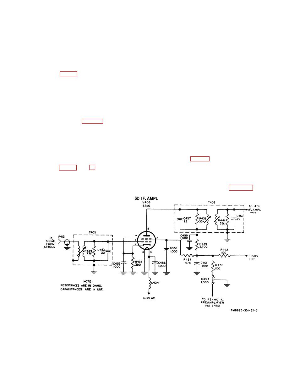
a. Interstate Transformers T405 ( f i g .
AT401.
31). The attenuated if. signal at connector
AT401J2 on the if. step attenuator is con-
47. If. Step Attenuator AT401
ducted through connector plug P412 and a
l e n g t h of coaxial cable, to the primary
w i n d i n g of interstage transformer T405.
The output of the 42-mc if. preamplifier
The primary winding has a 50-ohm imped-
i s coupled through connector plugs P409
a n c e . The secondary winding and shunt
a n d P410, part of coaxial cable assembly
c a p a c i t o r C453 resonate together at the
W403, to input jack J1 on the if. step at-
i n t e r m e d i a t e frequency, with R434 func-
tenuator subassembly. This circuit is
tioning as a load resistor. The trans-
i d e n t i c a l and interchangeable with the if.
f o r m e r T405 secondary is connected to
s t e p attenuator previously described for
the grid of third if. amplifier V406.
tuning unit 2 (para 39). The attenuated if.
b. If. Amplifiers V406 through V408.
signal is available at output jack J2 on the
Since the first three if. amplifiers are
i f . step attenuator subassembly for cou-
essentially the same, with identical values
pling through connector plug P412 to the
of circuit elements in their respective
input of the 42-mc if. amplifier subassem-
e l e c t r o d e s , the following circuit descrip-
bly.
t i o n for V406 is also applicable to V407
and V408 (fig. 101). The only difference is
48. If. Amplifier, Detailed Analysis
the use' of a 50-oh.m impedance-matching
transformer at the input to V406.
( 1 ) Cathode bias is developed by the
The 42-mc if. amplifier subassembly
v o l t a g e drop across R435 in the
h o u s e s interstage transformer T405, four
t h i r d if. amplifier (fig. 31). Cap-
amplifiers V406 through V409 operating at
Figure 31. Tuning unit 3, third if. amplifier V406, schematic diagram.
67
|
|
Privacy Statement - Press Release - Copyright Information. - Contact Us |
