 |
|||
|
|
|||
|
Page Title:
Figure 28. Tuning unit 3 rf amplifier and oscillator, schematic diagram. |
|
||
| ||||||||||
|
| 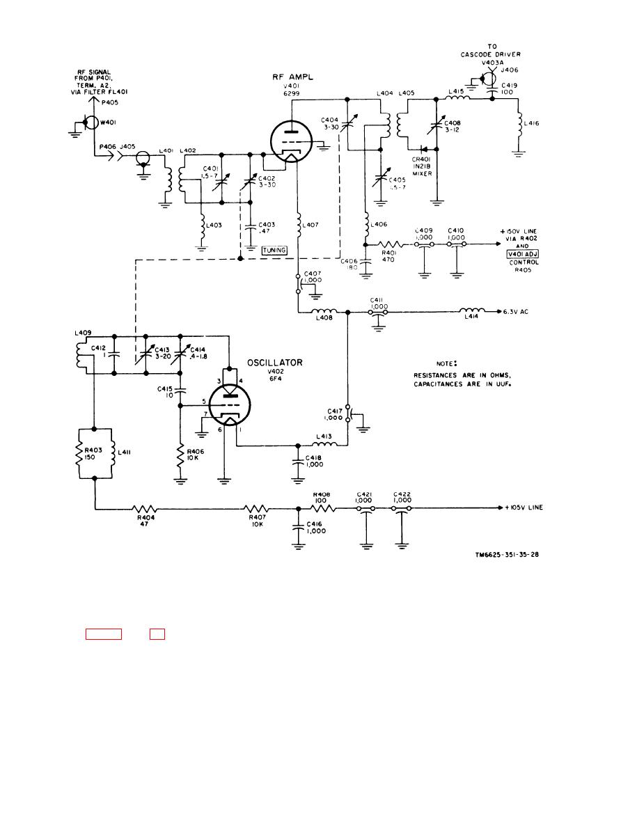 Figure 28. Tuning unit 3 rf amplifier and oscillator, schematic diagram.
rf amplifier cathode input and plate output
44. Oscillator V402, Detailed Analysis
circuits. Oscillations are developed in the
V402 tuned path circuit which consists of
A tuned plate oscillator which employs an
c o i l L409, fixed capacitor C412, tuning
a c o r n , type 6F4 (V402), generates an rf
capacitor C413, and trimmer capacitor
frequency which is 42-mc higher than the
C 4 1 4 . Feedback from the plate (pins 3
i n p u t signal frequency. The oscillator is
and 4) to the grid (pin 5) is made through
tuned by capacitor C413, which is mechan-
capacitor C415. Resistor R406 is the grid
i c a l l y coupled to C402 and C404 in the
62
|
|
Privacy Statement - Press Release - Copyright Information. - Contact Us |
