 |
|||
|
|
|||
|
Page Title:
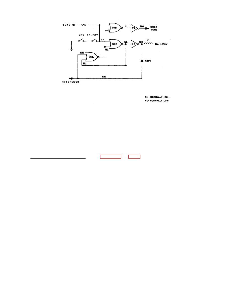
Figure 2-9. Interlock Logic Equivalent Circuit |
|
||
| ||||||||||
|
|  TM 11-5895-1141-34
Figure 2-9. Interlock Logic Equivalent Circuit
matched at every instant by a current fed back from the output of operational amplifier stage U1D via resistor R2 to the
inverting input terminal Ul-l1 of the operational amplifier. This terminal is thus maintained at a virtual null and thereby
maintains at least 50 dB of isolation between the various selector modules connected to this point, preventing crosstalk
between them. The audio voltage at the output of the operational amplifier U1D, being proportional to the current through
resistor R2, represents the sum of all received signals contributing to the headset amplifier bus. Capacitor C2 in parallel
with resistor R2, reduces the closed loop gain at frequencies beyond those handled by the channel radio equipment.
Operational amplifier U1D is biased sufficiently to accommodate the largest expected signal excursion by the current
through resistor R1.
(2) Loudspeaker Summing Amplifier. Refer to figure 2-10 and FO-10. U5 is an operational amplifier, wired in the
inverting configuration, which functions the same way as operational amplifier stage U1D described in the headset
summing amplifier. The total of the received signal currents that are routed by the various selector modules to the
loudspeaker amplifier bus which enters this module at P1-8 are matched at every instant by the current fed back from the
output through resistor R44. Consequently, the inverting output terminal is held at a virtual null, providing isolation
between the various selector modules feeding this point, while the audio voltage at the output of operational amplifier U5
represents the sum of these signals. The quiescent voltage of this stage is held at +12 volts by the biasing network
resistors R42, R45 and capacitor C21 to which the input resistors R43 and R46 are returned. Capacitors C22 and C24
serve to limit the open-loop and closed-loop gain at
2-23
|
|
Privacy Statement - Press Release - Copyright Information. - Contact Us |
