 |
|||
|
|
|||
|
Page Title:
Section V. LRU KNOB(s) REMOVAL AND REPLACEMENT PROCEDURES |
|
||
| ||||||||||
|
|  TM 11-5830-263-20&P
SECTION V
LRU KNOB(s) REMOVAL AND REPLACEMENT PROCEDURES
4
TYPICAL
VIS LRU
3
2
1
POINTER
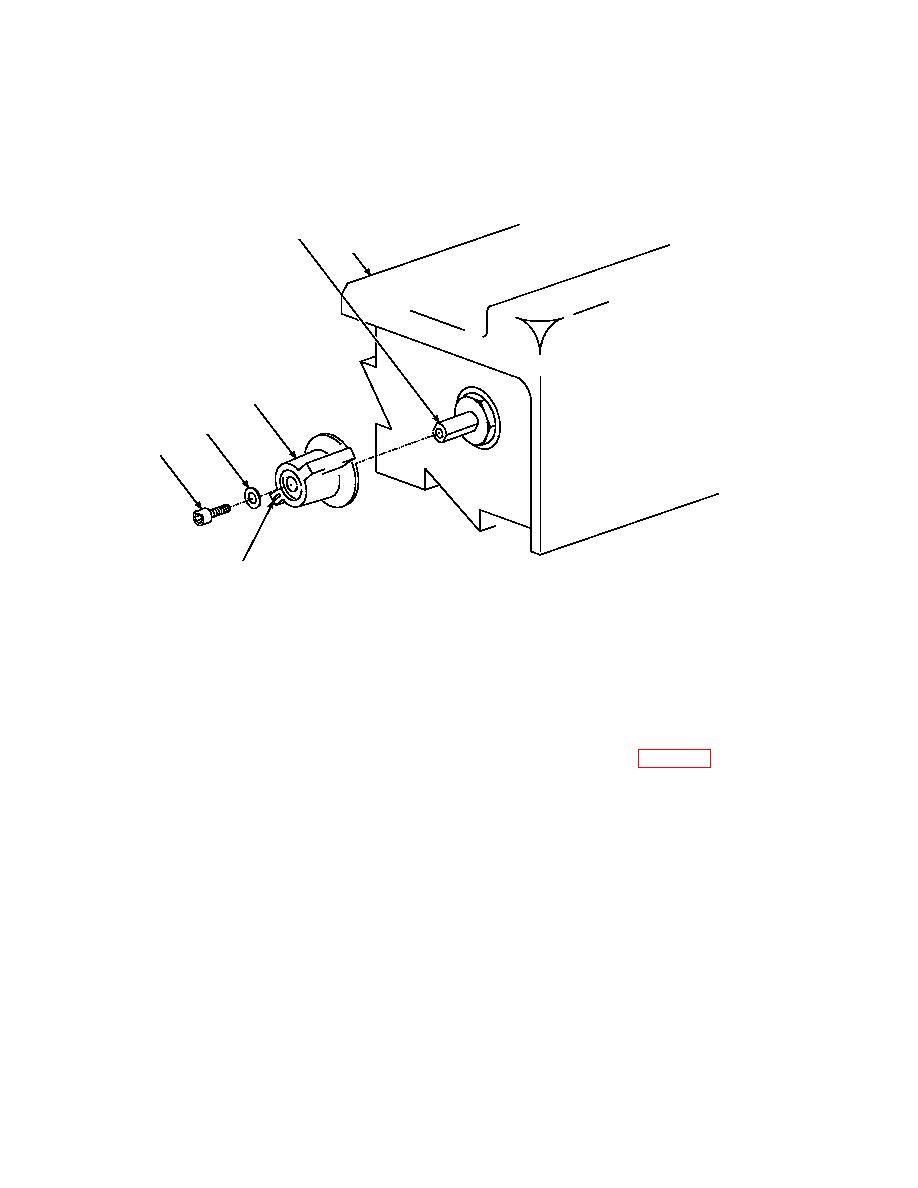
CAUTION
WHEN REMOVING OR REPLACING KNOBS, HOLD KNOB FIRMLY WITH ONE
HAND WHILE ROTATING SCREW WITH THE OTHER HAND SO AS TO NOT OVER
TORQUE THE SHAFT OF THE SWITCH.
3.11.
MCS, FFCS, AND MOS KNOB REMOVAL AND REPLACEMENT (Fig. 3-28)
The following procedures describe how to remove and replace control knobs on the MCS, FFCS, and
MOS. The control knobs (piece parts) utilized by the MCS, FFCS, and MOS are identical
a. Removal
1. Turn knob to a counterclockwise position until it comes to a full stop. The luminescent pointer
should be pointed down and to the left.
2. Using a socket head screw key remove socket head screw (1) and washer (2) from shaft (4).
3. Slide knob (3) from shaft (4).
b. Replacement
1. Slide knob (3) fully onto shaft (4) and turn counterclockwise until knob comes to a full stop.
The luminescent pointer should be pointed down and to the left.
2. Place washer (2) onto socket head screw (1) and install onto shaft (4).
3. Using a socket head screw key tighten socket head screw (1) onto shaft.
|
|
Privacy Statement - Press Release - Copyright Information. - Contact Us |
