 |
|||
|
|
|||
|
Page Title:
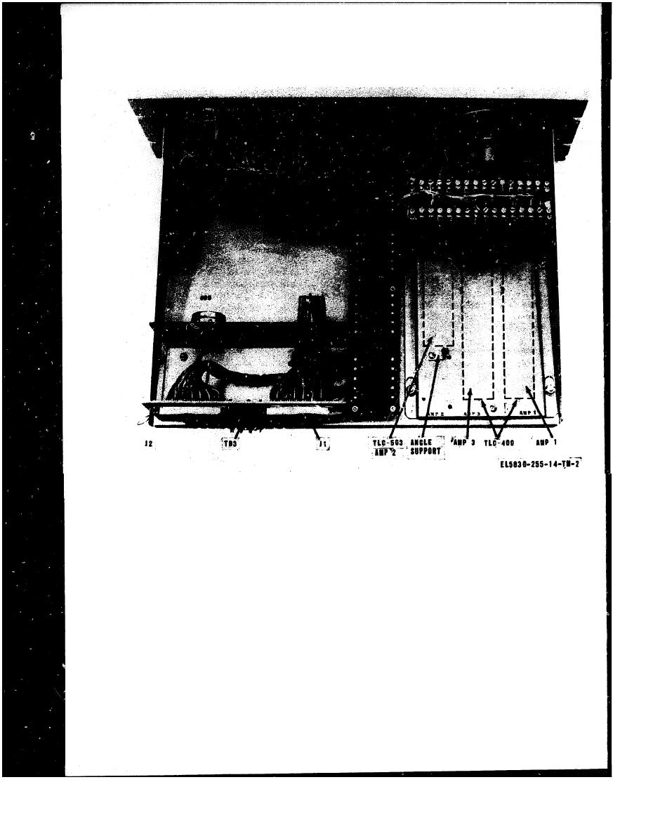
Figure 2-1. Central intercom, internal view. |
|
||
| ||||||||||
|
|  TM 11-5830-255-14
the positive lead to terminal No. 1 and the nega-
tive lead to terminal No. 2.
a. General. Installation at some locations may
CAUTION
require deviations from the details and instruc-
Make certain the power switch feeding
tions described in this paragraph for a typical
the equipment is turned off.
Intercom station. Prior to installation, review
each power distribution and wiring layout for
(4) Connect the external cable (from the
any deviation required from these instructions.
station main-frame (CDF) to connector plug P1
which mates with J1 on the rear of the unit.
b. Central Intercom Unit.
Likewise, connect a cable from the main-frame
(1) Install each central intercom unit into
to connector plug P2 which mates with J2. Make
the designated relay rack at the location at which
certain that the VF (T and R leads) are con-
it is to be used.
nected as a cable pair.
(2) Fasten the unit in place with four fil-
(5) Perform installation check as described
lister head screws and cup washers.
in paragraph 2-7.
(3) Connect the station power source of 48
c. Remote Intercom Unit.
volts dc to terminals 1 and 2 of TB3, the barrier
(1) Install each remote intercom unit into
strip at the rear of the unit (fig. 2-l). Connect
|
|
Privacy Statement - Press Release - Copyright Information. - Contact Us |
