 |
|||
|
|
|||
|
Page Title:
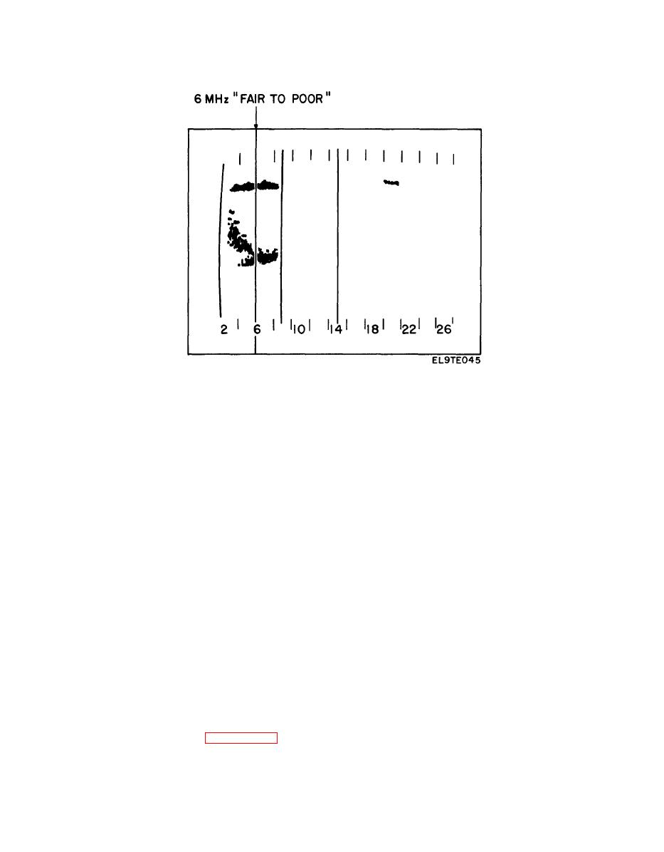
FIGURE 7-13. Example of Communications via Fading Spread F Multipath. |
|
||
| ||||||||||
|
|  TM 11-5820-917-13
FIGURE 7-13. Example of Communications via Fading Spread F Multipath.
far better than use of traditional methods. It can be limited more by factors
such as personnel motivation, communications equipment characteristics, and the
complement of assigned frequencies than any frequency management procedures.
Such procedures must be tailored to each application, however the following guide-
lines have been shown by years of field experience to be effective in a variety
of situations:
a. The Chirpsounder receiver should be placed at the center of communications
control. Up to three paths can be sounded using a single receiver. The (up to)
three Chirpsounder transmitters should be colocated with the communications trans-
mitters at the remote sites, and the diplexer feature considered to reduce antenna
requirements and to factor antenna patterns into the Chirp sounder measurements.
b. If the RSS-4 Spectrum Monitor is used, it should be colocated with the
Chripsounder receiver. If a remote site is over 2000 km away, it is advisable
to place an RSS-4 there, also.
c. If more paths are to be frequency-managed than there are Chirpsounder
systems available, the sounded paths must be chosen carefully. Experience has
shown that propagation conditions from location 1 to locations 2 and 3 are virtually
identical (except occasionally for Es) where 2 and 3 are within 100 km radius of
location 1 provided both paths are over land or over sea water. For paths of longer
length, azimuth and potential propagation differences become major factors. For
example, assume the situation of managing the HF circuits to the six locations sur-
rounding R as shown in figure 7-14 with only 3 Chirpsounder transmitters. Propa-
gation on paths to 1, 2 or 3 should be virtually identical. Circuits to 4 and 5
|
|
Privacy Statement - Press Release - Copyright Information. - Contact Us |
