 |
|||
|
|
|||
|
|
|||
| ||||||||||
|
|  TM 11-5820-873-34
CHAPTER 3
DIRECT SUPPORT
Section I. GENERAL
3-1. Scope
checkout/troubleshoot for the antenna coupler CU-
This chapter contains checkout, troubleshooting, repair,
2229/URC-92.
removal, replacement and other maintenance
authorized for direct support of Radio Set AN/URC-92.
3-2. Voltage Measurements
The checkout and troubleshooting procedures are
separated into a checkout/troubleshoot for the receiver
Applicable voltages and acceptable tolerances are listed
transmitter
RT-1277/URC-92
and
a
in Table 3-1
Section II. TOOLS AND EQUIPMENT
3-3. Test Equipment
Table3-1 Voltage Measurements
0VDC 0.2
12 VDC 0.8
Refer to TM 11-5820-873-12, Appendix D, TM
2VDC 0.5
22 VDC 1.5
11-5820-873-20P and TM 11-5820-873-34P Also,
3VDC 025
28 VDC 1.5
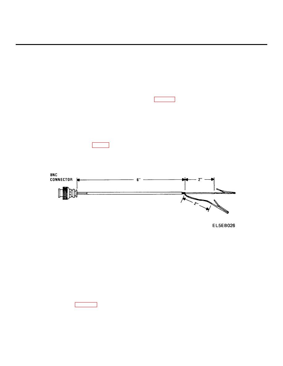
a BNC to clip lead cable is required (Fig 3 -1)
5 VDC 0.25
7.7VDC 08
9VDC 0.8
12VAC 0.8
9.56VDC 0.8
20VAC 1.5
10 VDC 0.8
115 VAC 15
Figure 3-1 BNC/Clip Lead Cable.
Section III. CHECKOUT/TROUBLESHOOT
The procedures correspond with the authorized
3-4. General
maintenance level at direct support. Following any
This section contains checkout and troubleshooting for
repair action, the test technician must return to step 1 of
both the receiver-transmitter and the antenna coupler.
the checkout unless directed differently by the
Completion of a checkout signifies a particular unit is
procedure.
The troubleshooting does not consider
operationally ready for use. Troubleshooting procedures
incorrect or missing supply voltages to subassemblies.
are designed to function from incorrect indications in the
Before any replace/repair action is accomplished on a
checkout.
subassembly, the test technician should verify all
3-5. Receiver-Transmitter RT-1277/
necessary supply voltages at the subassembly. Refer to
URC-92 Checkout/Troubleshoot
List of Illustrations for the appropriate schematic.
Incorrect or missing supply voltages are not authorized
The following procedures in Table 3-2 will establish the
for repair at this maintenance level. If supply voltage
operational readiness of RT-1277/URC-92 receiver-
malfunctions are noted, route the Receiver-Transmitter
transmitter. Successful completion of the checkout
RT-1277/URC-92 to the next higher maintenance level
portion indicates the receiver-transmitter Is operationally
for repair.
ready for use. Troubleshooting procedures are designed
to function from incorrect indications in the checkout.
3-1
|
|
Privacy Statement - Press Release - Copyright Information. - Contact Us |
