 |
|||
|
|
|||
|
Page Title:
Section II. DIRECT SUPPORT MAINTENANCE |
|
||
| ||||||||||
|
|  TM 11-5820-401-35-1/NAVELEX 0967-432-3020
resistors for transistors Q81 and Q82, respec-
Q81. The amplified output of transistor Q81 is
tively, Resistors R87, R98, and R90 are bias resis-
direct-coupled to the base of transistor Q82 which,
tors for transistors Q82 and Q83. Capacitor C85
in turn, applies the signal to the base of transistor
is a high audio frequency bypass capacitor.
Q83. Resistor R92 reduces the level of the signal
from transistor Q83. Capacitor C88 is a coupling
c. The microphone amplifier uses degenerative
capacitor.
ac and dc feedback to stabilize the operation of
b. The dc voltage for the A80 is fed from the
the transistors. Capacitors C84 and C86 and re-
sistors R85, R88, and R91 form the ac feedback
25.5-volt dc power supply through filter network
circuit. Resistor R88 is the principle component
consisting of resistor R93 and capacitor C87.
of the dc feedback circuit from the emitter of
Resistors R82 and R83 set the base voltage on
transistor Q83 to the emitter of transistor Q81.
transistor Q81. Resistors R84 and R86 are load
Section II.
DIRECT SUPPORT MAINTENANCE
(1) Multimeter TS-352B/U.
3-4. General
The C-2299/VRC is maintained at organizational
(2) Toolkit,
E l e c t r o n i c Equipment TK-
(TM 11-5820-401-12), direct support, and depot
100/G.
maintenance levels. Repair parts for the C-2299/
VRC are listed in appendix C.
b. Test Facilities. Either test facility in (1)
or (2) below may be used to check the perform-
ante of the C-2299/VRC.
Required
a. Test Equipment and Tools.
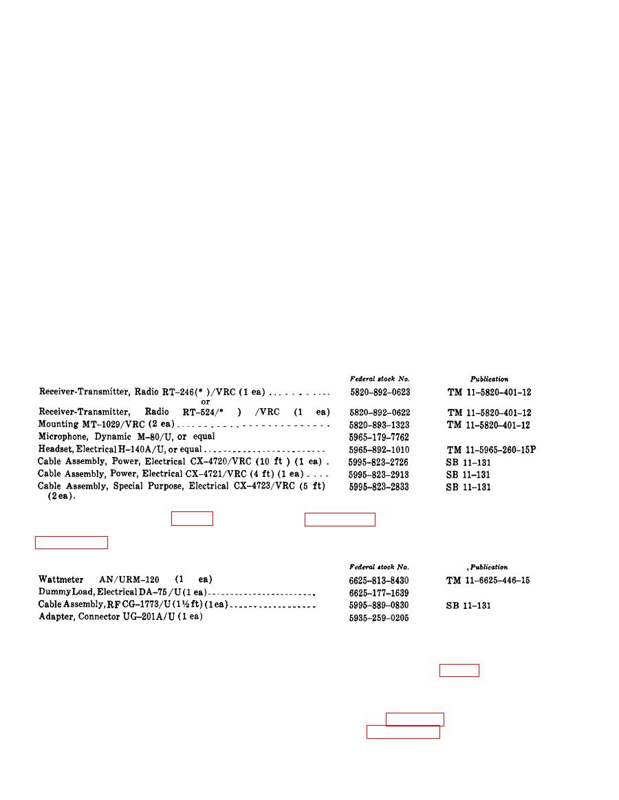
(1) Radio set facility.
Item
use the test box to test the C-2299/VRC, refer to
tion, the following dummy antenna items are
required.
Item
to the radio sets ((1) below) or to the test box
((2) below).
C-2299/VRC
Use the procedures in b or c below to troubleshoot
radio sets will be used to troubleshoot the C-
and check the performance of the C-2299/VRC.
2299/VRC, proceed as follows.
Set up the equipment as explained in a(1) or (2)
(a) Connect the C-2299/VRC to the radio
below.
sets as shown in figure 31. The required items
a. Test Setup. Connect the C-2299/VRC either
are listed in paragraph 35b (1).
|
|
Privacy Statement - Press Release - Copyright Information. - Contact Us |
