 |
|||
|
|
|||
|
Page Title:
A2000 CRS ASSEMBLY MECHANICAL ADJUSTMENT. |
|
||
| ||||||||||
|
|  TM
11-5820-401-34-3/0967-LP-432-3
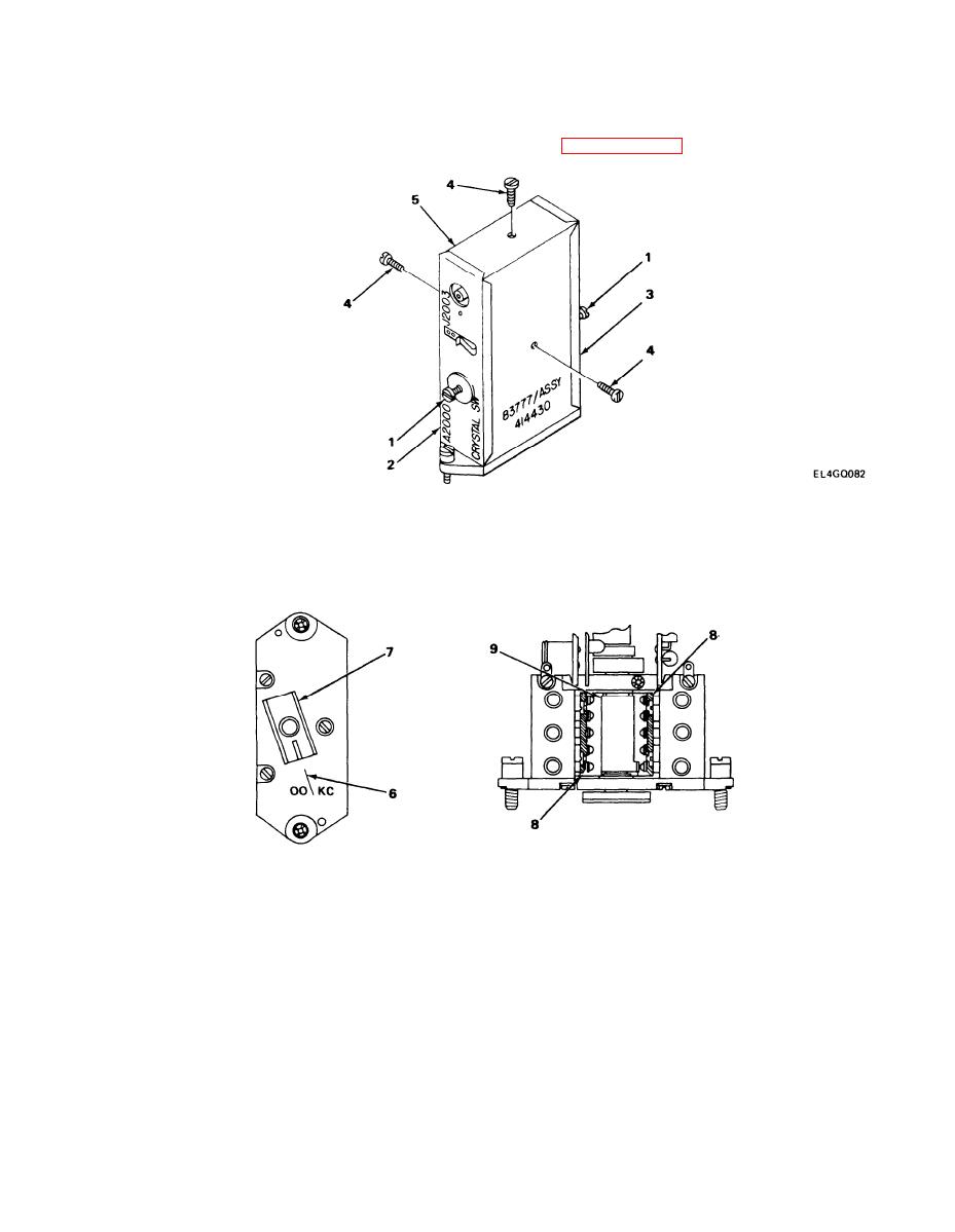
6-7. A2000 CRS ASSEMBLY MECHANICAL ADJUSTMENT.
PRELIMINARY PROCEDURE: Remove A2000 assembly, (See paragraph 2-12.)
DISASSEMBLY
1. Using screwdriver, loosen two captive screws (1) and remove top cover (2) and bottom
cover (3).
2. Using screwdriver, remove three screws (4) and U-shaped cover (5).
EL4GQ078
ADJUSTMENT
NOTE
The OO/KC scribe mark (6) on assembly chassis is alined with scribe mark on the A2000
coupler (7) to provide a starting point or reference during adjustment of point overlap.
This represents the angular rotation of the A2000 coupler (7) in relation to contacts on
Switch S2001 (8) that are closed by the S2001 cam (9).
8-21
|
|
Privacy Statement - Press Release - Copyright Information. - Contact Us |
