 |
|||
|
|
|||
|
|
|||
| ||||||||||
|
|  TM 11-5820-401-34-3/0967-LP-432-3060
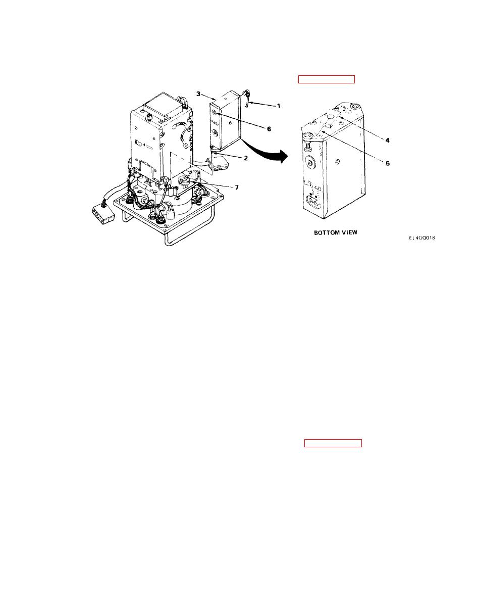
A2000 ASSEMBLY REPLACEMENT.
2-12.
MATERIALS/PARTS: Radio Frequency A2000 Oscillator Assembly
PRELIMINARY PROCEDURE: Remove top and bottom covers. (See paragraph 2-7.)
NOTE
Front panel is removed to eliminate possibility of damaging color-coded pins on A1000
assembly.
REMOVAL
1. Disconnect orange wire (W103) (1) from J2001.
2. Using screwdriver, loosen two captive screws (2).
3. Remove A2000 assembly (3).
INSTALLATION
1. Aline coupler (4) with scribe mark (5).
2. Install A2000 assembly (3) so that J2003 terminal (6) faces top of radio.
3. Aline coupler (4) with mating coupler (7). Coupler (4) may have to be turned slightly to mate
with coupler (7).
4. Using screwdriver, tighten two captive screws (2).
5. Connect orange wire (W103) (1) to J2001.
FOLLOW-ON MAINTENANCE: Replace top and bottom covers. (See paragraph 2-7.)
2-23
|
|
Privacy Statement - Press Release - Copyright Information. - Contact Us |
