 |
|||
|
|
|||
|
|
|||
| ||||||||||
|
|  TM 11-5820-401-34-3/0967-LP-432-3060
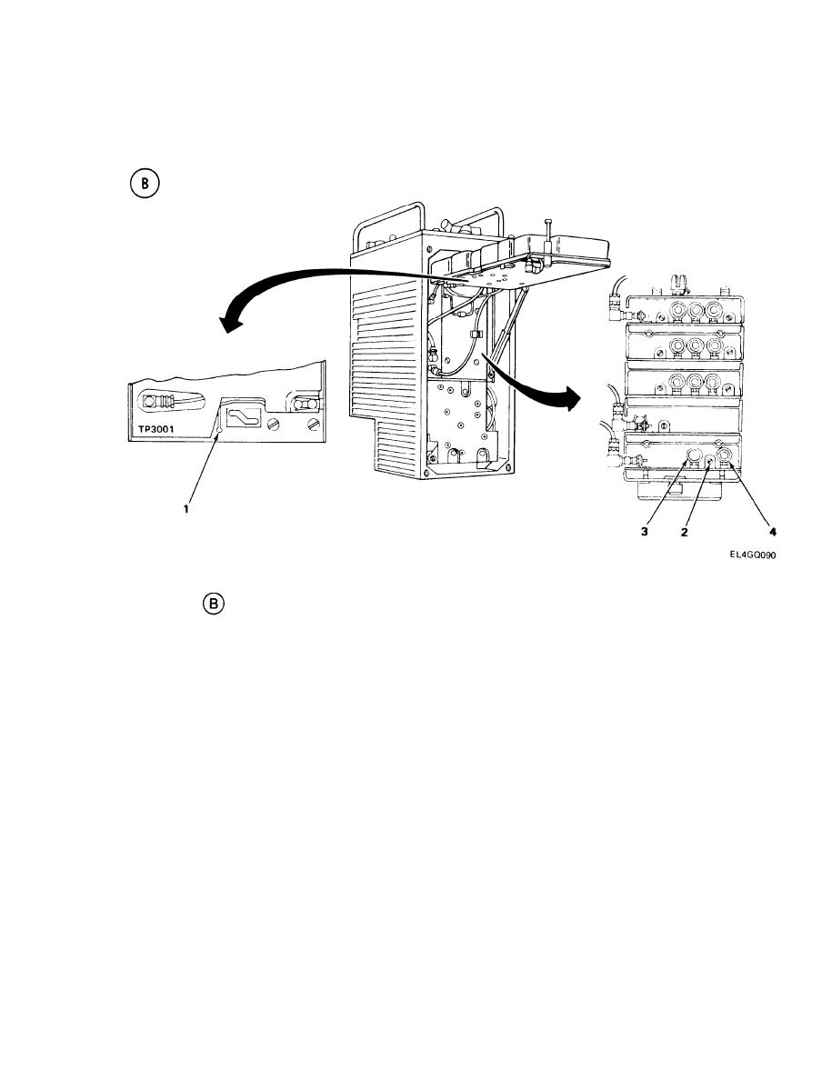
5-16.
LOCAL OSCILLATOR A1500 ALINEMENT. (CONT)
ALINEMENT PROCEDURE
Connect ME-26(*)/U positive lead to TP3001 (1) and negative lead to --ground. (See test setup
1.
diagram
.)
Adjust C1501 (2) for clear audio tone and zero-volt reading on ME-26(*)/U. Zero-volt reading
2.
means zero deflection from 1.5 v center of scale.
Set R-442/VRC MC-TUNE-KC control to 30.00 MHz.
3.
Connect AN/USM-207 to T-connector.
4.
Adjust AN/URM-103 RF TUNING control for 30.00-MHz output.
5.
NOTE
30 MHz. The rf level must be increased temporarily to enable the frequency counter to
display. Adjust the AN/URM-103 RF TUNING control as necessary, reset to 100-v rf
level; then disconnect the T-connector from the counter.
Adjust L1502 (3) for clear audio tone and zero-volt reading on ME-26(*)/U.
6.
Set R-442/VRC MC-TUNE-KC control to 52.00 MHz.
7.
Connect AN/USM-207 to T-connector.
8.
Adjust AN/URM-103 RF TUNING control for 52.00-MHz output.
9.
5-95
|
|
Privacy Statement - Press Release - Copyright Information. - Contact Us |
