 |
|||
|
|
|||
|
|
|||
| ||||||||||
|
|  TM 11-5820-401-34-3/0967-LP-432-3060
LOCAL OSCILLATOR A1500 ALINEMENT. (CONT)
5-16.
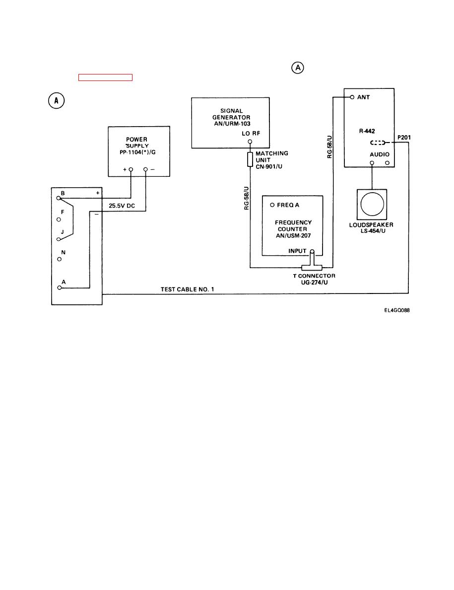
TEST SETUP. Connect the equipment as shown in test setup diagram
. Remove R-442/VRC top
cover. (See paragraph 2-7.) Connect P1004 to J1004 on the A3000 tray.
INITIAL EQUIPMENT CONTROL SETTINGS. Change the final settings used in the CRS Test as
follows:
Set AN/URM-103 RF OUTPUT switch to 0-10 KUV.
1.
Adjust AN/URM-103 RF TUNING control for 42.00-MHz output.
2.
NOTE
42 MHz. The rf level must be increased temporarily to enable the frequency counter to
display. Adjust the AN/URM-103 RF TUNING control as necessary, reset to 100-V rf
level; then disconnect the T-connector from the counter.
Set R-442/VRC MC-TUNE-KC control to 42.00 MHz.
3.
4.
Adjust AN/URM-103 DEVIATION control for 8-kHz reading on DEVIATION KHZ meter.
5-94
|
|
Privacy Statement - Press Release - Copyright Information. - Contact Us |
