 |
|||
|
|
|||
|
Page Title:
RECEIVER AUDIO RESPONSE TEST (X.-MODE). |
|
||
| ||||||||||
|
|  TM 11-5820-401-34-3/0967-LP-432-3060
RECEIVER AUDIO RESPONSE TEST (NORMAL MODE. (CONT)
5-8.
STANDARD. ME-30(*)/U should indicate between 14 and 22 volts.
26. If ME-30(*)/U indicates below 14 volts or above 22 volts, see troubleshooting chart 5-5.
RECEIVER AUDIO RESPONSE TEST (X.-MODE).
5-9.
PURPOSE. This test is similar to the R-442/VRC Receiver Audio Response Test (Normal Mode).
When set up for X-mode, however, the receiver responds to a wider band of frequencies because the
A5000 tray is not used. The ability of the R-442/VRC to detect and respond flatly to the desired
intelligence is verified by:
1.
Injecting 1-kHz modulation into the R-442/VRC ANTENNA port, while measuring the voltage at
pin L (X-MODE IN) of Test Cable No. 1.
2.
Changing the modulation rate to 500 Hz, 3 kHz, 5 kHz, and 10 kHz, while taking db readings
at pin L (X-MODE IN) of Test Cable No. 1.
3.
Comparing the db readings taken in step 2 to the reference voltage taken in step 1 to see
if the standard is met.
R-442/VRC X-MODE SETUP PROCEDURE
1.
Remove bottom cover from R-442/VRC. (See paragraph 2-7.)
2.
Raise A4000 tray and secure brace.
3.
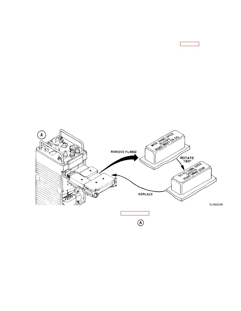
Remove Filter FL4002. (See X-MODE setup diagram
.)
4.
Rotate Filter FL4002 180 degrees.
5.
Put Filter FL4002 back into tray.
Set X-MODE NORMAL Switch S4001, located underneath A4000 tray, to X-MODE position
6.
7.
Release brace and lower tray.
Replace R-442/VRC bottom cover.
8.
5-25
|
|
Privacy Statement - Press Release - Copyright Information. - Contact Us |
