 |
|||
|
|
|||
|
|
|||
| ||||||||||
|
|  TM 11-5820-401-34-3/0967-LP-432-3060
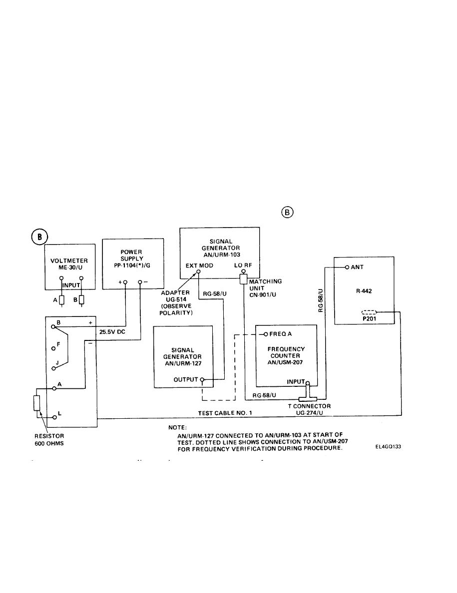
RECEIVER AUDIO RESPONSE TEST (X- MODE). (CONT)
5-9.
TEST EQUIPMENT AND MATERIALS
Adapters (two) UG-274B/U
Power Supply PP-1104(*)/G
(T-Connector) and UG-514
Frequency Counter AN/USM-207
Matching Unit CN-901/U
Signal Generator AN/URM-103
Rf Cables (three) RG-58/U
Signal Generator AN/URM-127
Test Cable No. 1
Ac Voltmeter ME-30(*)/U
Resistor, 600-ohm 5%, 2-watt
NOTE
The 600-ohm resistor provides an impedance matching load for the audio transformer.
The resistor is used in place of Loudspeaker LS-454/U, which would issue a loud,
distracting tone when the R-442/VRC VOLUME control is adjusted during the test. If no
600-ohm resistor is available, however, the loudspeaker must be connected.
TEST SETUP. Connect test equipment as shown in test setup diagram
Turn on test equipment. Allow at least 15 to 30 minutes for warmup.
INITIAL EQUIPMENT CONTROL SETTINGS. Set equipment controls as ;ndicated in the following
table. If using alternate test equipment, adjust for 64.00 MHz, 20-v rf input level, 1-kHz modulation,
and 8-kHz frequency deviation.
5-26
|
|
Privacy Statement - Press Release - Copyright Information. - Contact Us |
