 |
|||
|
|
|||
|
Page Title:
Isolating Trouble in Module A15 |
|
||
| ||||||||||
|
|  through (7) above and adjust T2 un-
c. Faulty Parts Isolation.
(1) Insert the module extender into the
til the indications given in (4) and
A15 connector and insert A15 into
(6) above are equal. Perform this
step as required.
the module extender.
(2) Place the function switch on there-
(9) Replace module A9.
ceiver-tansmitter at ON. Meas -
ure the voltages at the points out-
lined in the charts in (a) and (b)
below. Compare them with the nor-
mal signal and dc voltages listed.
Note: Measure all voltages to ground.
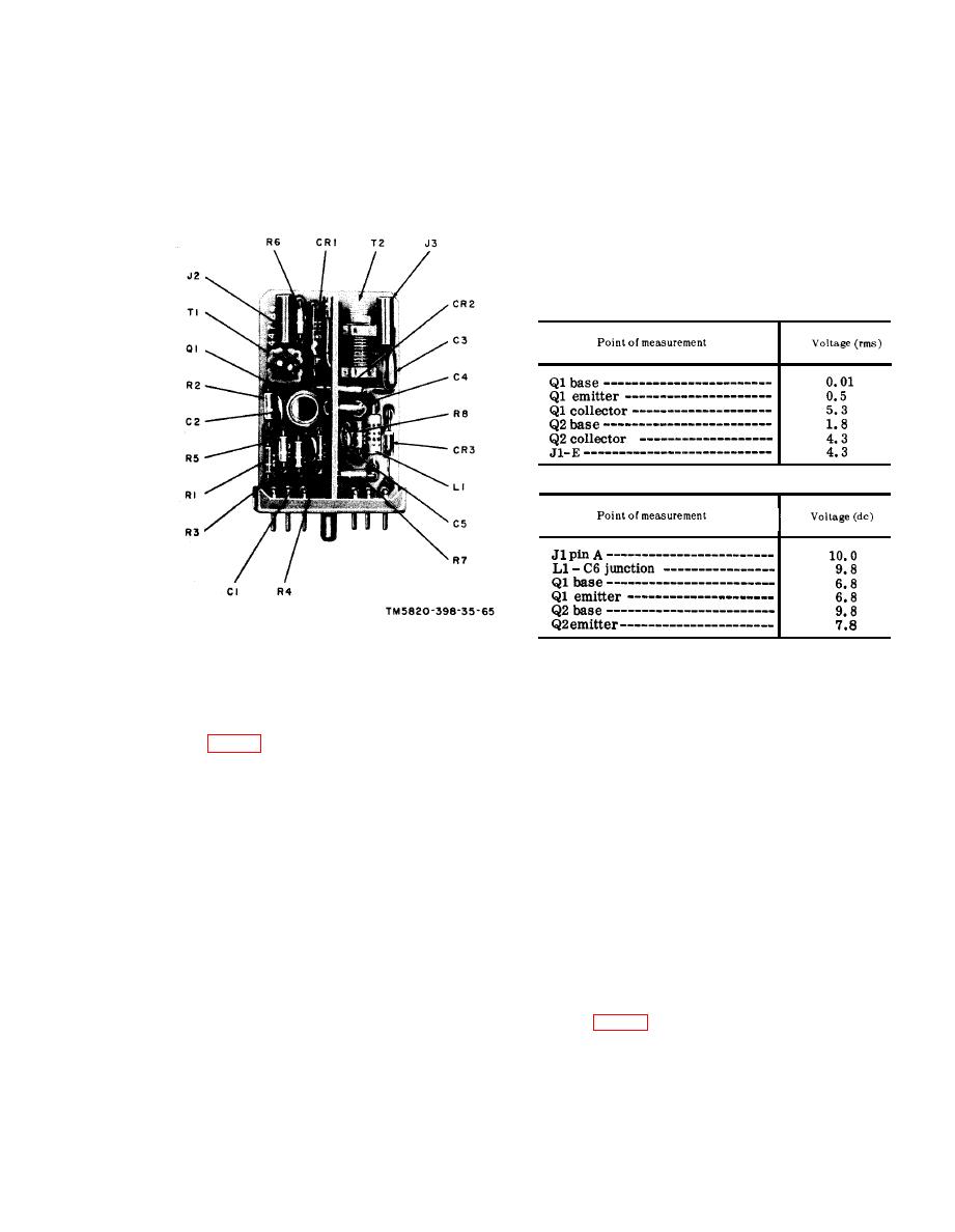
(a) Signal voltage chart.
(b) Dc voltage chart.
(3) After the replacement of a faulty
Figure 66. Module A14, parts location.
part, perform alignment proce-
dures given in d and e below and
repeat the procedure given in a and
b above.
d. Alignment Procedure. With A15 ex-
t e n d e d (c(1) above), set the receiver-
a. Preparation.
transmitter front panel controls as fol-
(1) Prepare the following equipment:
lows :
(1) BAND switch at 30-52.
(b) Voltmeter, Meter ME-30A/U.
(2) Tuning knobs to 30.00 mc.
(c) Oscilloscope AN/USM-50A.
(3) Function switch at ON.
(d) Multimeter ME-26B/U.
e. Alignment Procedure.
(e) Module extender.
(1) Connect the AN/USM-26 between
(2) Set the receiver-transmitter front
A14J3 and chassis ground.
panel controls as follows:
(2) Adjust A15T1 until the AN/USM-26
(a) BAND switch at 30-52.
indicates 1.0000 mc 25 cps.
(b) Tuning knobs to 30.00 mc.
(3) Remove the module extender.
(c) Function switch at ON.
b. Output Frequency and Output Level
Test. Connect the AN/USM-26 between
A14J3 and chassis ground. The AN/USM-
50A should indicate a minimum of 1.5 volts
a. Preparation.
peak-to-peak.
(1) Insert the module extender into J11
|
|
Privacy Statement - Press Release - Copyright Information. - Contact Us |
