 |
|||
|
|
|||
|
Page Title:
Isolating Trouble in Transmitter Power Amplifier Circuit |
|
||
| ||||||||||
|
| 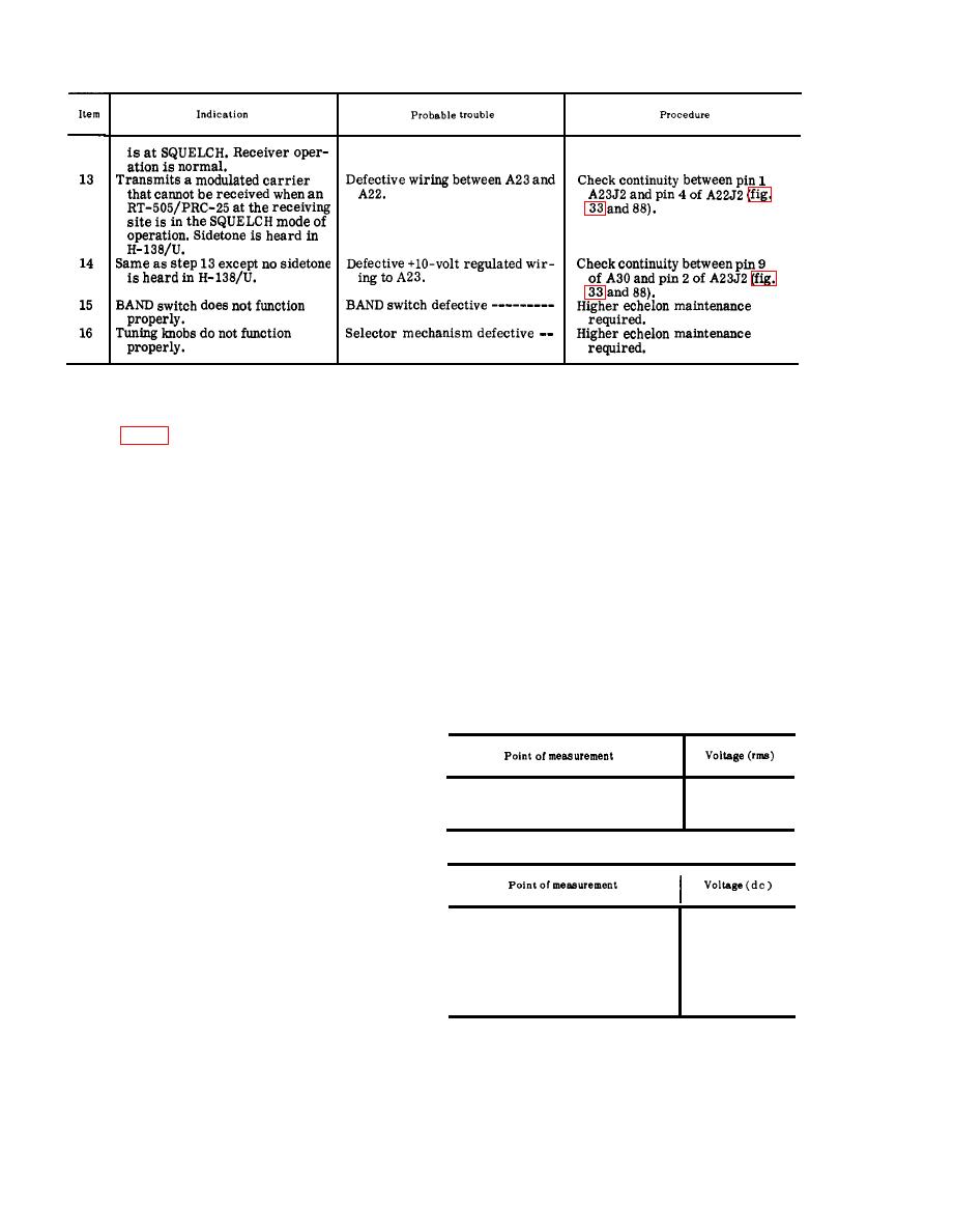 (9) Repeat (6) and (7) above.
(10) If the output does not meet the
Amplifier Circuit
standards outlined in (1) and (6)
above, proceed to c below.
a. Preparation.
c. Faulty Parts Is elation.
(1) Prepare the following equipment:
(1) Connect the AN/URM-43A to ANT
(a) Multimeter ME-26B/U.
connector J2. Connect the H-138/U
to an AUDIO connector.
(c) Handset H-138/U.
(2) Set the BAND switch at 30-52 and
(2) Set the front panel controls of the
set the tuning controls for 30.00
receiver-transmitter as follows:
mc.
(a) BAND switch at 30-52.
(3) Press the H-138/U push-to-talk
(b) Tuning controls for 30.00 mc.
switch and measure the voltages
(c) Function switch at ON.
at the points listed in the chart
(3) Connect the AN/URM-43A to ANT
below. Compare them with the nor-
connector J2.
mal signal and dc voltages listed.
(4) Connect the H-138/U to an AUDIO
Note: Measure all voltages to ground.
connector.
(a) Signal voltage chart.
b. Output Power Test.
(1) Press the H-138/U push-to-talk
switch. The AN/URM-43A should
indicate 2 watts.
16
A29-5 ---------------------
(2) Release the H-138/U push-to-talk
16
A29V1-8 -------------------
switch.
A29V1-3 - - - - - - - - - - - - - - - - - -
68
(3) Set the receiver-transmitter tun-
(b) Dc voltage chart.
ing controls for 52.95 mc.
(4) Repeat (1) and (2) above.
(5) Set the front panel controls of the
receiver-transmitter as follows:
+125
A29-2 ---------------------
(a) BAND switch at 53-75.
-45
A29-7 ---------------------
+2.5
A29-4 ---------------------
(b) Tuning controls for 53.00 mc.
A29V1-5 - - - - - - - - - - - - - - - - - -
+2. 5
(6) "Press the H-138/U push-to-talk
A29V1-7 - - - - - - - - - - - - - - - - - -
+2. 5
switch. The AN/URM-43A should
A29V1-3 - - - - - - - - - - - - - - - - - -
+118
A29-5 ---------------------
-10.2
indicate 1.5 watts.
A29V1-8 -------------------
-10.2
(7) Release the H-138/U push-to-talk
(4) After the replacement of a faulty
switch.
part, perform the procedures given
(8) Set the receiver-transmitter tun-
in a and b above.
ing controls for 75.95 mc.
|
|
Privacy Statement - Press Release - Copyright Information. - Contact Us |
