 |
|||
|
|
|||
|
Page Title:
Frequency Synthesizer System First Mixer Module A14 |
|
||
| ||||||||||
|
|  41.45-mc to 64.45-mc output of the
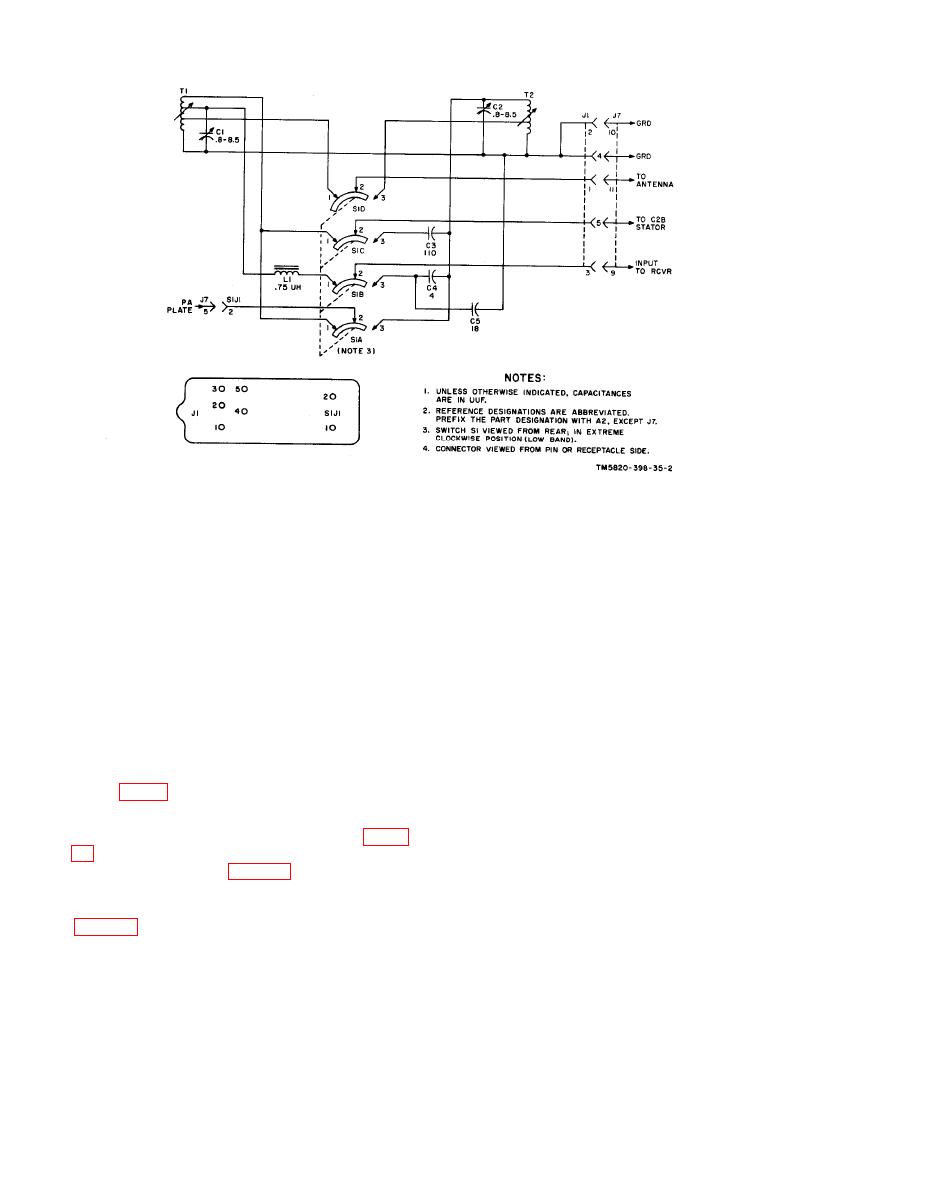
c. The tuning controls tune inductors
fss buffer in A9. The combination
L1, L2, and L3, which are in series with
of resistors R1 and R2 plus the
capacitors C2, C1, and C3, respectively,
input impedance to Q1 provides the
to resonate the antenna in the low and high
bands. When the BAND switch is in the low
proper termination for the vfo buf-
fer amplifier. Capacitor Cl is a
position, inductor L3 and capacitor C3 are
coupling capacitor. The amplifier
placed in the circuit; when the BAND switch
output of Q1 is coupling capacitor.
is in the high position, inductors L1 and
The amplified output of Q1 is
L2 and capacitors C2 and Cl are placed in
c o u p l e d to the fss first mixer
the circuit.
transformer T1. Resistor R6 in-
creases the frequency response of
T1.
Mixer Module A14
(2) Resistors R3 and R4 form a voltage
divider which develops the fixed
The fss first mixer module, A14, heter-
portion of the emitter-to-base bias
odynes the output of vfo module A9 (para
for transistor Q1. Resistor R5 is
the emitter swamping resistor.
erator module A15 (para 23) to produce a
Capacitor C2 is an rf bypass ca-
band of frequencies around 53 mc. This
pacitor for the emitter of Q1.
output is supplied to the 53-mc filter A13
b. The signal inducted to the secondary
windings of transformer T1 is coupled
fss first buffer amplifier and a mixer
through push-pull diodes CR1 and CR2 to
circuit.
the tuned primary of transformer T2. Ca-
a. Fss First Mixer Buffer Q1.
pacitor C3 and the primary of transformer
T2 form a tuned circuit. The input from
(1) Fss first mixer buffer Q1 provides
1-mc spectrum generator A15 is applied
isolation and low-power gain. It
has sufficient bandwidth to pass the
26
|
|
Privacy Statement - Press Release - Copyright Information. - Contact Us |
