 |
|||
|
|
|||
|
|
|||
| ||||||||||
|
|  rf power output should be not less
the TS-497/URR until the ME-30B/U indi-
than 16 watts.
cates 12.25 volts across the 600-ohm load
(7) Recycle the rt unit to 399.9 mc and
(the MICROVOLTS control setting must
then back to the test frequency. Key
not exceed 6).
the rt unit and measure the unmod-
e. Record the db reading on the ME-30B/
ulated power output. The power
U that corresponds to 12.25 volts.
f. Turn the TS-497/URR modulator
output should be within 5 percent of
16 watts.
switch to OFF.
(8) Repeat step (7) above for test fre-
g. The ME-30B/U indication must be at
quencies of 300 and 235 mc.
least 10 db below the value recorded in e
b. TransmitterFrequency Resettability.
above.
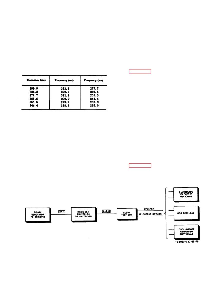
(1) Connect the equipment as shown in
h. Perform steps a through g above for
the following test frequencies:
(2) Apply 115 (or 230) volts ac (AN/
TRC-68) or 26.4 volts dc (AN/VRC-
24) to the rt unit.
(3) Tune the rt unit to a test frequency
of 225.0 mc and allow a 30-minute
warmup period.
(4) Key the rt unit and measure the
output frequency. The output fre-
quency should be within 2 kc of
225.0 mc.
(5) Recycle the rt unit to 399.9 mc and
a. Rf Power Output Resettability.
then back to the test frequency. Key
the rt unit and measure the output
(1) Connect the AN/URM-43A to the
rt unit ANT. jack.
frequency. The output frequency
(2) Place the rt unit in its case. Place
should be within 2 kc of the test
frequency.
the AN/VRC-24 on Mounting MT-
(6) R e p e a t (5) above for test fre-
1436/U.
(3) Apply 115 (or 230) volts ac to the
quencies of 300 and 235 mc.
c. Receiver Sensitivity Resettability.
AN/TRC-68 or 26.4 volts dc to the
(1) Connect the equipment as shown in
AN/VRC-24.
of 225.0 mc.
(2) Apply 115 (or 230) volts ac (AN/
(5) Allow 2 hours for warmup.
T R C - 6 8 ) or 26.4 volts dc (AN/
(6) Key the rt unit. The unmodulated
VRC-24) to the rt unit.
|
|
Privacy Statement - Press Release - Copyright Information. - Contact Us |
