 |
|||
|
|
|||
|
Page Title:
Alignment of Uhf Injection Subunit Step Tuner |
|
||
| ||||||||||
|
|  the turns of L222 for a maximum
(2) Set the ME-26/U to -3-volt dc
voltage on ME-26/U.
range and connect the dc probe
to test point J201 (fig. 53).
Note. To gain access to L222, loosen
c. Procedure.
the three retaining screws on the uhf injec-
tion subunit and remove the subunit from
the main frame (para 108). Do not discon-
22 to 39 end correspond to the numbers on the
nect plug P4 or plug P201. Be careful not
MANUAL FREQUENCY TENS control.
to ground the exposed terminal of C1 which
(1) Set the MANUAL FREQUENCY
is directly behind the uhf subunit. Capac-
TENS control to 39.
itor C1 is connected to the 300-volt supply.
(2) Tune trimmer inductance L218
(4)
MANUAL FREQUENCY
Set the
TENS control to 22.
marked 39 on the first oscillator
(5) Tune C208 (fig. 48) for maximum
rear plate (fig. 48) for maximum
voltage on the ME-26/U.
voltage on the ME-26/U.
(6) Set the MANUAL FREQUENCY
(3) Set the MANUAL FREQUENCY
TENS control to 39.
TENS control to 38 and tune trim-
(7) Repeat procedures (3) through (6)
mer inductance L217 (fig. 50)
above, until no increase in voltage
through the hole marked 38 (fig. 48)
on the ME-26/U is obtained at posi-
for maximum voltage on the ME-
tions 22 and 39 of the MANUAL
26/U.
FREQUENCY TENS control.
(4) Continue through the frequency
range of the MANUAL FRE-
QUENCY TENS control and, at each
Frequency Tripler and Amplifier
position, tune the corresponding
trimmer inductance (fig. 48) for
a. Test Equipment Required.
(1) Multimeter ME-26/U.
maximum voltage on the ME-26/U.
(2) Radio Frequency Wattmeter AN/
USM-43A.
Tuner
(3) Alignment tool.
(4) Tab-bending tool.
a. Test Equipment Required.
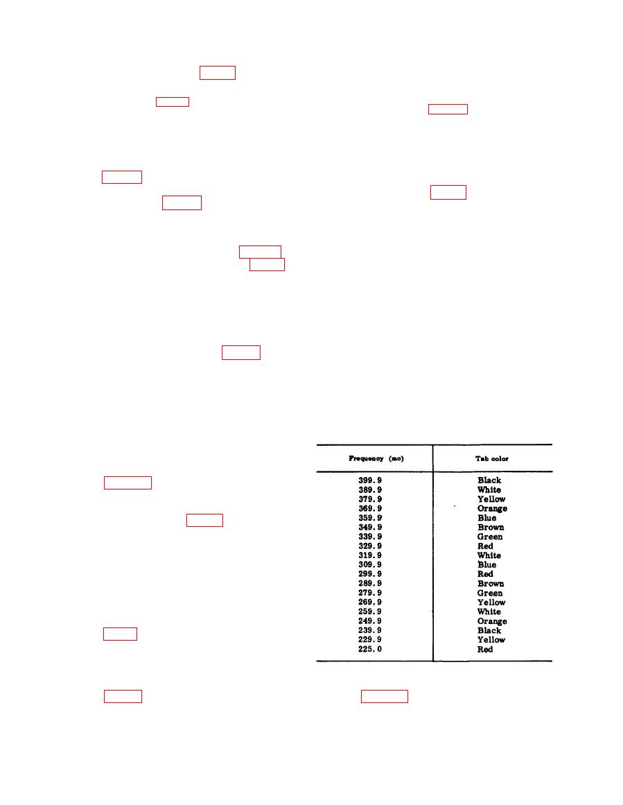
b. Tab Identification Chart.
(1) Multimeter ME-26/U.
(2) Alignment tool.
b. Test Setup.
(1) Perform the alignment test setup
(2) Set the ME-26/U to the -3-volt dc
range and connect the dc probe to
test point J201 (fig. 53).
Note. The voltage at J201 will be ap-
proximately twice the amplitude between
225.0 and 299.9 mc that it is between
300.0 and 399.9 mc.
c. Procedure.
(1) Set the MANUAL FREQUENCY
TENS control to 39.
(2) Rotate trimmer capacitor C208
oscillator rear plate counterclock-
wise to its stop.
(3) Adjust L222 through the hole in the
c. Test Setup.
(1) Perform the alignment test setup
bottom of the first oscillator cover
|
|
Privacy Statement - Press Release - Copyright Information. - Contact Us |
