 |
|||
|
|
|||
|
Page Title:
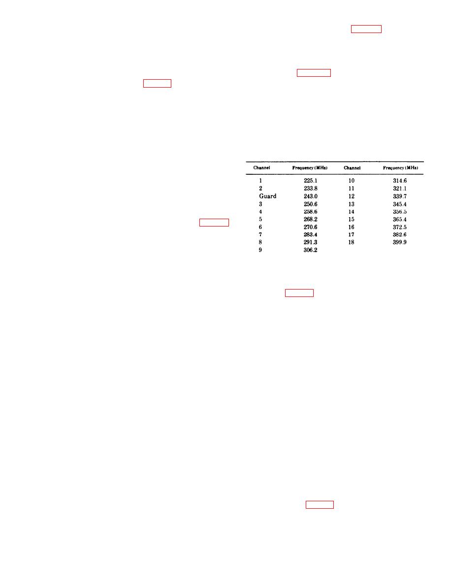
Table D-2. List of Test Frequencies |
|
||
| ||||||||||
|
|  (5) Power outpug. Refer to figure 1 and connect
titude. Pressure loss shall not exceed 4 pounds per
the RF Wattmeter to the antenna jack J-13 of the
square inch.
Receiver-Transmitter unit using an approximate
(3) Electrical tests. Interconnect the Receiver-
length of (10 feet of RG-9/V) cable. At each fre-
Transmitter RT-742/ARC-51BX or RT-742B/ARC-
quency listed in table D-2, observe that the frequency
51BX and the control C-6287/ARC-51X for the
selection is symmetrically displayed in the read out
Bench Tests as shown in figure 1, 2, and 3 as re-
windows of the control unit. Key the transmitter
quired. Use a RF Wattmeter AN/URM-43A or equiv-
and observe that the transmitter output as read on
alent in place of an antenna. Unless otherwise
the RF Wattmeter, is at least 16 watts. Also note that
specified use "VOL" and "SENS" controls in the
the average output for the 19 channels shall be at
maximum position only.
least 20 watts.
(4) Transmitter tests. For Receiver-Transmitter
RT-742/ARC-51BX use procedure (a), for Receiver-
Table D-2. List of Test Frequencies
Transmitter RT-742B/ARC-51BX use procedure
(b).
(a) Turn on the radio by setting the power
switch on the control to the T/R position. Allow the
set to warm up for approximately 5 minutes before
beginning the tests.
and allow a 5 minute warm up period. The RT-742B/
ARC-51BX has a duty cycle of 5 minutes transmit
and 10 minutes receive. During transmit operation,
(6) Sidetone tests. For Receiver-Transmitter
observe this duty cycle ratio. Connect the VTVM
RT-742/ARC-51BX use procedure (a) for Receiver-
(ME-30/U) on the + 10V scale to A6J2, turn the control
Transmitter RT-752B/ARC-51BX use procedure
head frequency to 399.9 MHz on the power ampli-
(b). Refer to figure 1.
fier. Key the transmitter and adjust C6-Z1, C12-
(a) Using not less than 3 widely separate fre-
Z2 and C18-Z3 on the RF preamplifier for maximum
quencies, key the transmitter and talk into the
voltage on the VTVM. Next connect the VTVM to
microphone. The audio output power is 100 milli-
A6J3 and adjust C5-Z1 trimmer on the power am-
watts. Listen to the sidetone output at the headset
H-101A/U to check for normal audio level charac-
plifier for maximum voltage. Adjust C14-Z2 trimmer
teristics. If questionable, check for proper operation
for maximum power out and unkey. Connect the
by feeding a 100 Hz signal into the DUM MIC Jack
VTVM with the positive lead to A6J7 and the ne-
with Audio Oscillator TS-382D/U, at a level of 3 db
gative lead to A6J6 on the power amplifier with the
below clipping (or 70% of clipping). The sidetone
transmitter unkeyed.
output should be indicated as not less than 14 milli-
CAUTION
watts at 30 percent modulation.
(b) Same as (a) above. When the signal input
There is 420 volts on A6J6 and J7 with re-
level on the audio oscillator is adjusted to 3 db below
spect to ground while the transmitter is
clipping the wattmeter shall read 100 milliwatts.
keyed. The VTVM must be isolated from
If the wattmeter does not read 100 milliwatts, ad-
ground.
just R42 (located on the audio module) until 100
(c) After the connections are made, key the
milliwatts is obtained. The sidetone output should
transmitter and adjust A6R11 V4 bias potentiometer
be indicated as not less than 14 milliwatts at 30
percent modulation.
on the power amplifier for 1.5 volts across A6J6 and
(7) Modulation tests. For Receiver-Transmitter
J7. Unkey and disconnect the VTVM. Starting at in-
RT-742/ARC-51BX use procedure (a), for Receiver-
dent 39 on the ten megacycle control proceed to 22
Transmitter RT-742B/ARC-51BX use procedure (b).
checking for power at each position, go back to 39
and perform the power check for the whole and tenth
ment as shown. Set the function switch of the con-
megacycle position. This checks all transmitter
trol unit to T/R + G position and allow the equipment
Xtals.
to warm up for at least 5 minutes. Adjust the audio
7
|
|
Privacy Statement - Press Release - Copyright Information. - Contact Us |
